First of all, sorry it’s been a while since my last post. More articles to come in 2016!
Since then, I did manage to take the Magic Cooler and use it to run the Christmas lights on my house with some minor upgrades to the software and minor updates in the cooler. If you’re not already familiar with the Magic Cooler, see it explained in Part1 and Part2 from previous posts.
https://www.youtube.com/watch?v=LBgu77rin3E
My daughter painted the sign showing what FM frequency to tune to to listen in (it was later changed to 88.3MHz since many tuners can’t handle ‘even’ frequencies). My son helped code up some of the songs.
The house was hooked up with 9 separate sets of lights. The nativity scene was the only one kept constant, the other 8 would be controlled by the music playing.
Lighting plan done in GIMP
Each note in the song is assigned to one or more of the relays that controls one of the light sections. This way synchronizing the music to the lights is much easier than the usual manual method of associating beats to music, although this method does require coding up each song manually. A side benefit is that you can involve those more familiar with reading music than C code to add new songs to the ‘mix’. More on the music-to-code methodology in another article (maybe I’ll make my first Instructable!).
The music is output to an FM transmitter instead of a speaker, so as to not bother the neighbors and to permit those driving by to listen to the music on their car radios.
Where the Magic Happens
Minor updates I did to the cooler in the pic above include:
Add an IDE ribbon cable to connect from the control signals at the bottom of the box up to the prototyping platform on top. These are connected to the middle breadboard, as to permit connecting any microcontroller board in the future if desired.
Switch added to go between Play and Test modes.
Momentary pushbutton (yellow) added to help test out the relays and various light connections. Repeatedly pushing thus button goes from all off, turns on relays one a time, then turns them all on (no relays actually activate when all are told to turn on due to current limitations of the system).
Extension USB cable added for USB hooked to Teensy control board to permit easy reprogramming of the board. Hope to upgrade in the future to permit wireless reprogramming or control of the board (as a side benefit I did figure out how to reprogram using Arduino IDE on my Chromebook using Crouton OS– very neat and portable!).
Updates I’d like to do:
Make PCB for the relatively constant parts of the control system– LED indicator lights, audio output, pushbutton and DIP switches.
Upgrade to solid state relays to permit more relays to be on at once.
Add LED to indicate which song is playing at the moment.
Add USB hub for easier 5V power distribution on prototyping platform.
Code updates to permit even completely automatic note-relay assignment.
Add WAV playing capability of each note so that it sounds better.
Add capability to play 4 part harmony type music (will sound better).
Make software library to make code easier to manage online, allow users to submit songs remotely.
Let me know if you have any other suggestions by giving a comment!
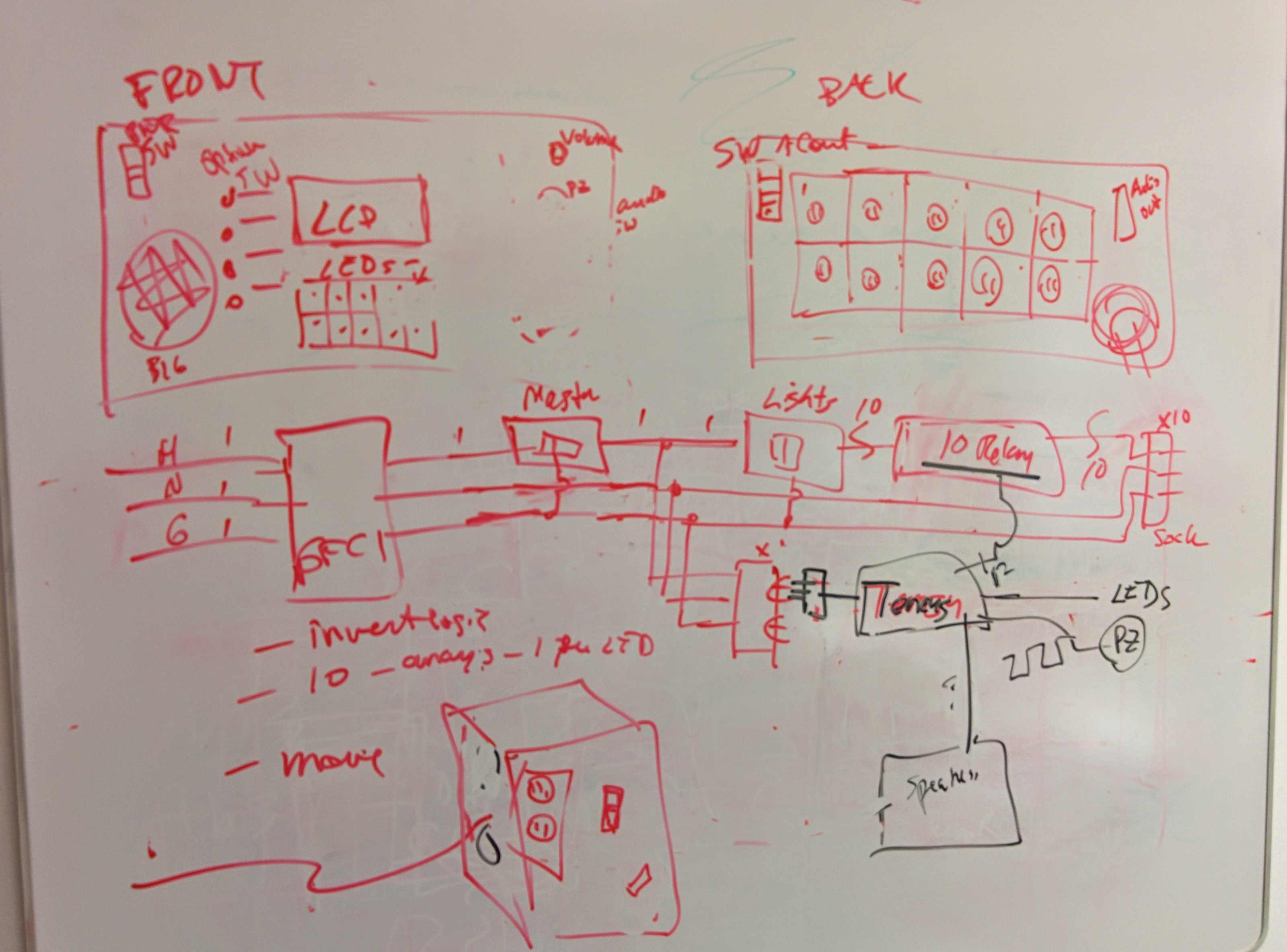
Thus far we have focused only on building the AC circuit that will serve to directly control the 10 switchable lights via 10 relays.
Now, we want to hook up the Teensy 3.1 board to control those relays in time to music, and have the Teensy drive the music itself out to a speaker of some sort. The Teensy 3.1 board uses the Freescale Kinetis K20 microcontoller.
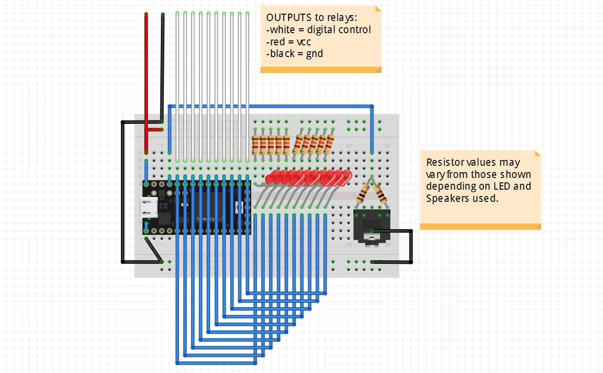
For controlling the relays, I used 10 of the Teensy board GPIOs. These were configured in software to serve as digital outputs. Since the relays used negative logic, i.e. a logic 0 activates the relay, the LEDs on the circuit were set up to also use negative logic so that the same GPIO on the Teensy board activates both an LED and a relay. The LEDs on the circuit protoboard will help in debugging any issues with the relays and give a reminder that the code is running properly. For this project, pins 13-22 were used for LED/relay control. (See the board pinout chart here). Pin 13 also controls an LED directly on the Teensy board– so we have yet another ‘heartbeat’ to remind that the code is running.
The speaker or headphones are connected to one of the PWM-capable outputs of the Teensy. PWM stands for Pulse-Width Modulation and basically is an output signal that looks like a square wave. The Arduino IDE tone() function used in the software permits generating a square wave of variable frequency. When this square wave is applied to a speaker, you get a sound of that frequency! For this project, PWM-capable pin 23 was chosen for sound output.
The diagram below shows how the Teensy protoboard circuit was wired up.
Teensy Circuit Protoboard
Appropriate valued resistors must be chosen for the above circuit depending on the LEDs and speaker used to limit the current through each. For my circuit, I used 1.3k ohm for the LEDs and 100 ohm for each of the 2 ‘channels’ of the headphone jack. 2 different resistors were connected to each of 2 sides of the jack in order to get stereo sound from the computer speakers.
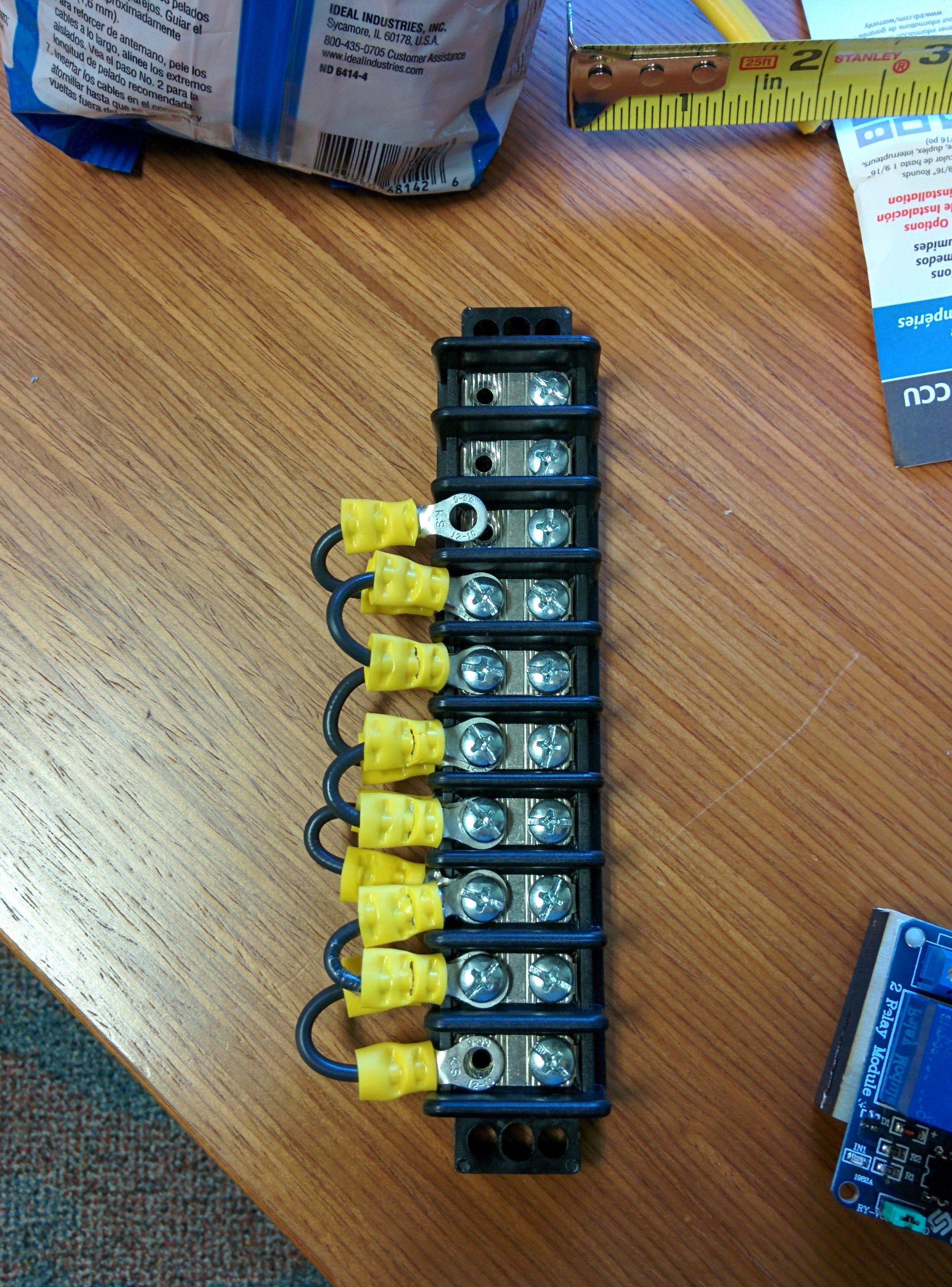
The top of the circuit diagram above shows the 12 wires that will serve to control the relays:
10x digital logic control of each relay (white)
vdd / power (red) (in actuality 2 of these were needed to power the 2 relay boards)
ground (black) (in actuality 2 of these were needed to ground the 2 relay boards)
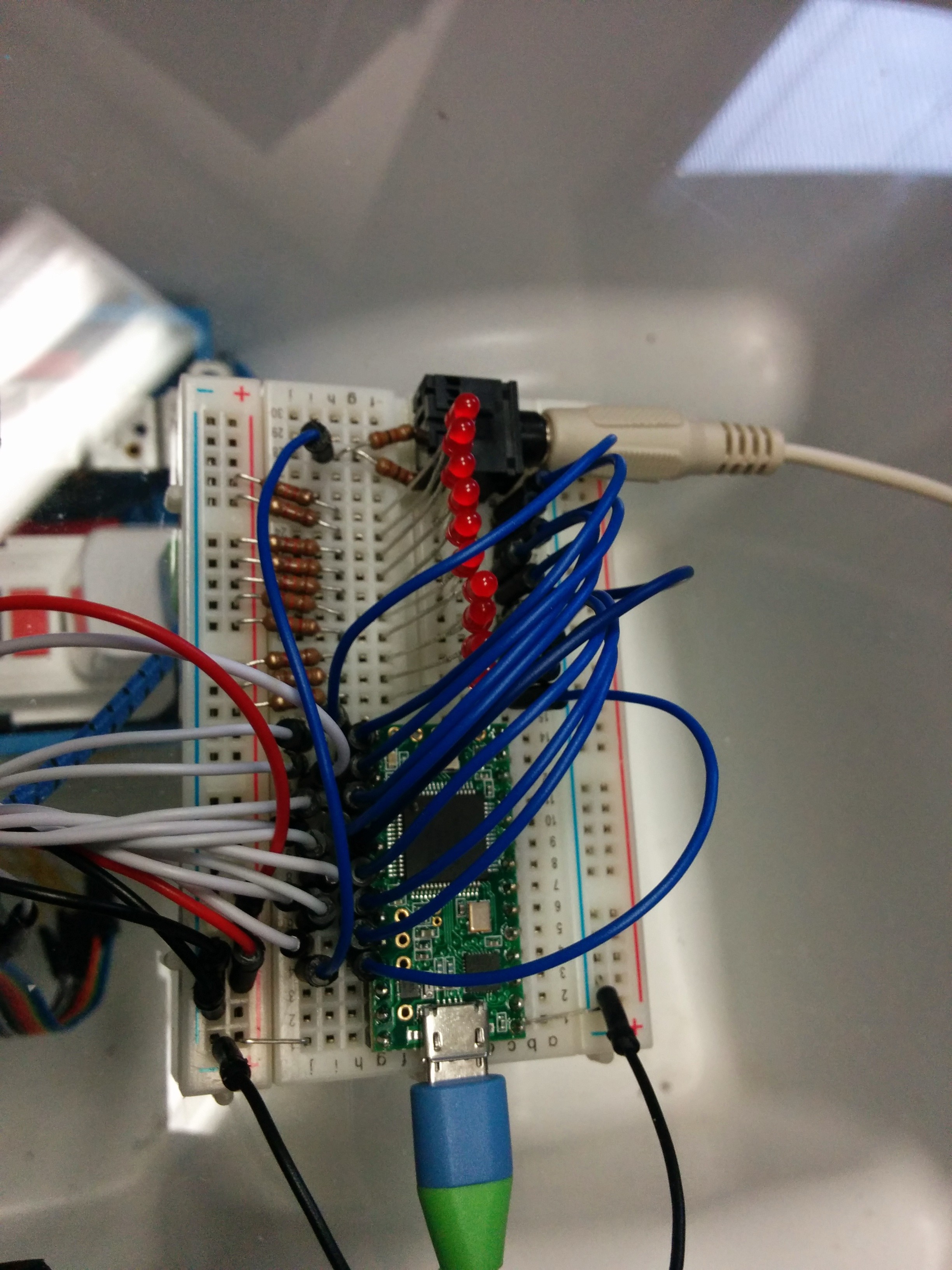
Here is the actual board used:
Shown with computer speaker wire connected
The board is powered by a standard micro USB cable connected to a USB AC adapter plugged into the ‘always on’ AC outlet.
Next, we hook up the board to a simple set of computer speakers to make sure it works:
https://www.youtube.com/watch?v=y0DAuEe6r7Q
(In this video you can still see the black speakers we were initially going to use attached to the side of the cooler, but we decided against them at the last minute. Computer speakers worked out just fine.)
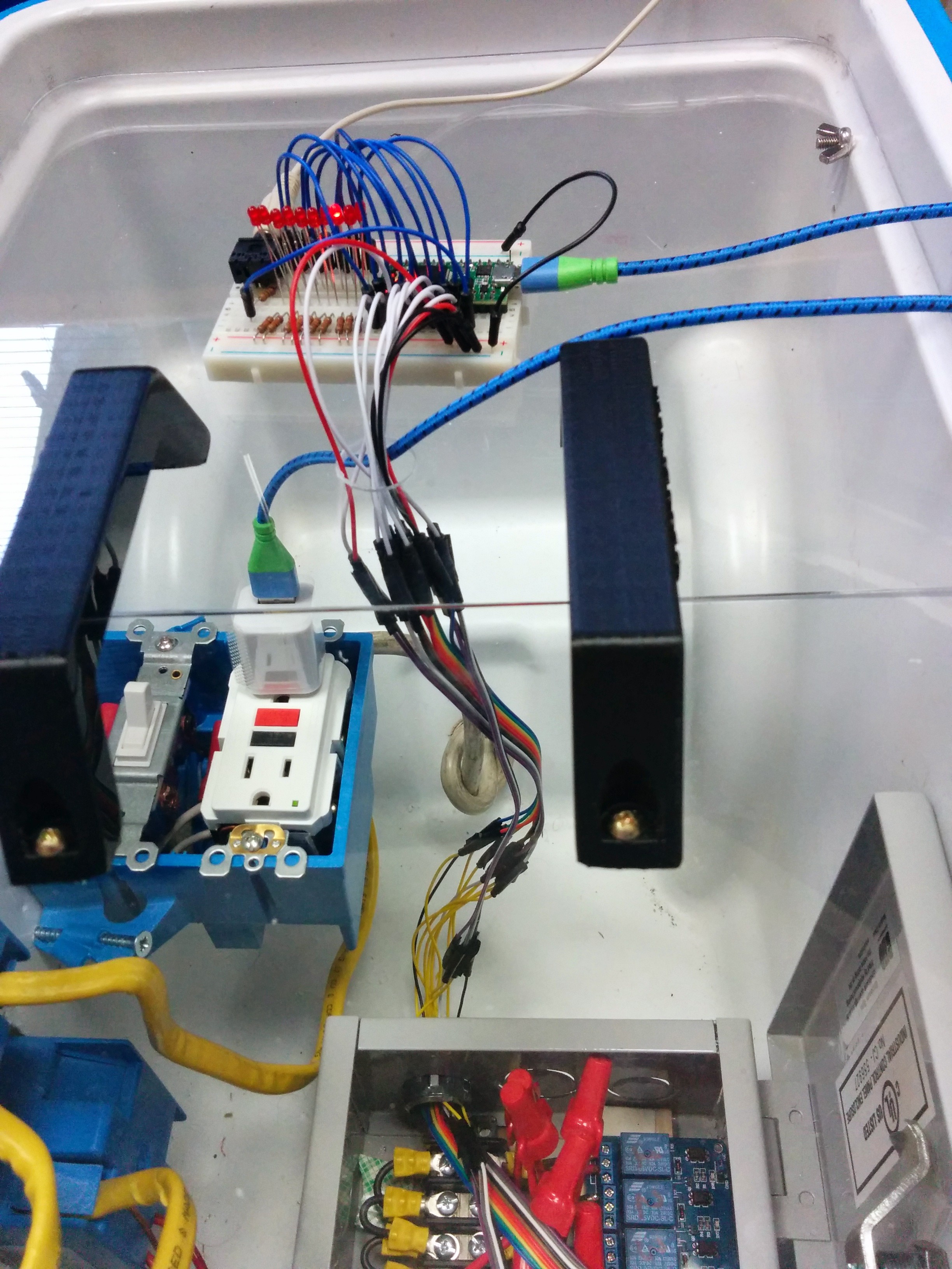
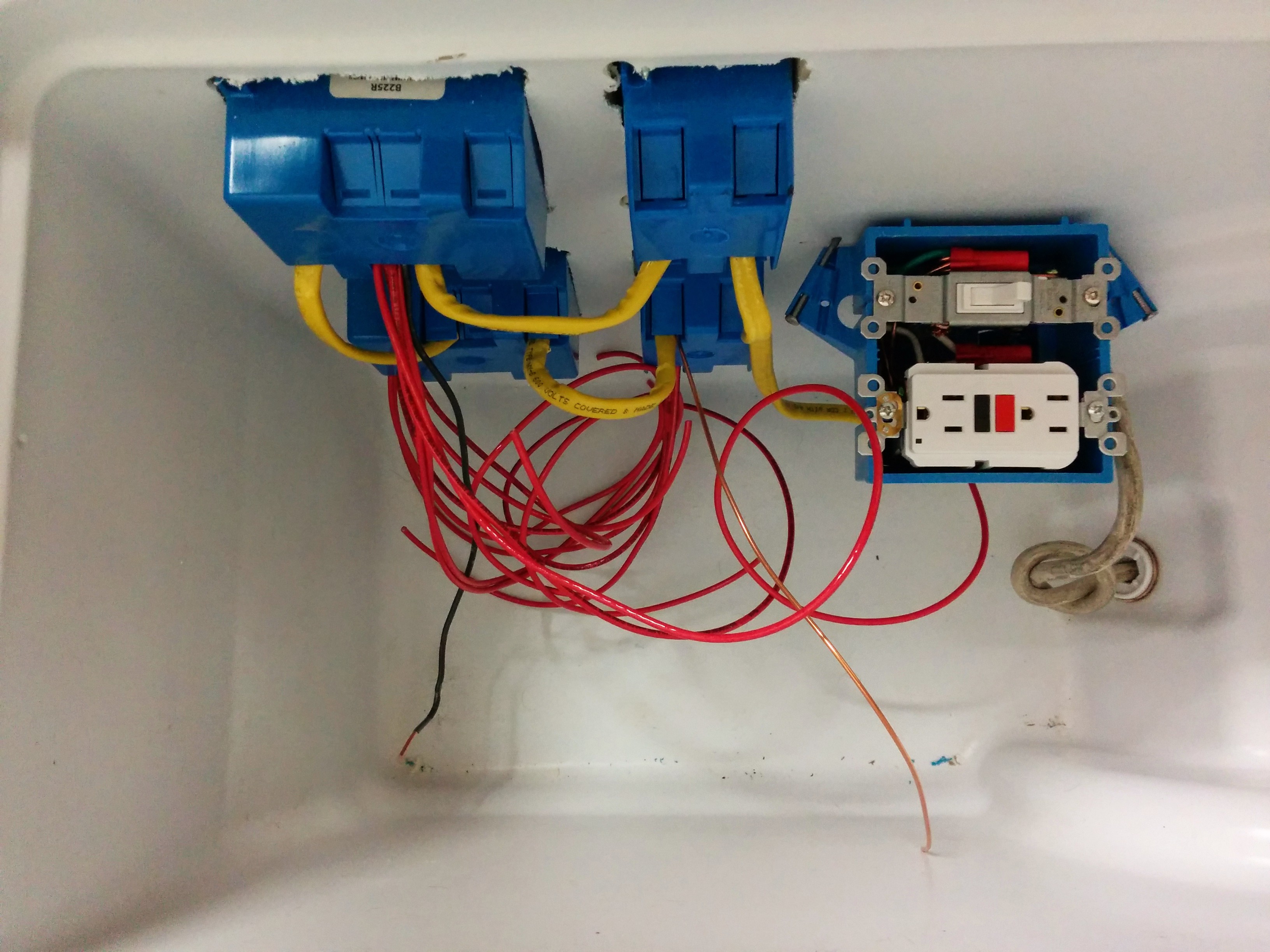
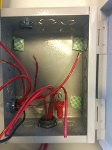
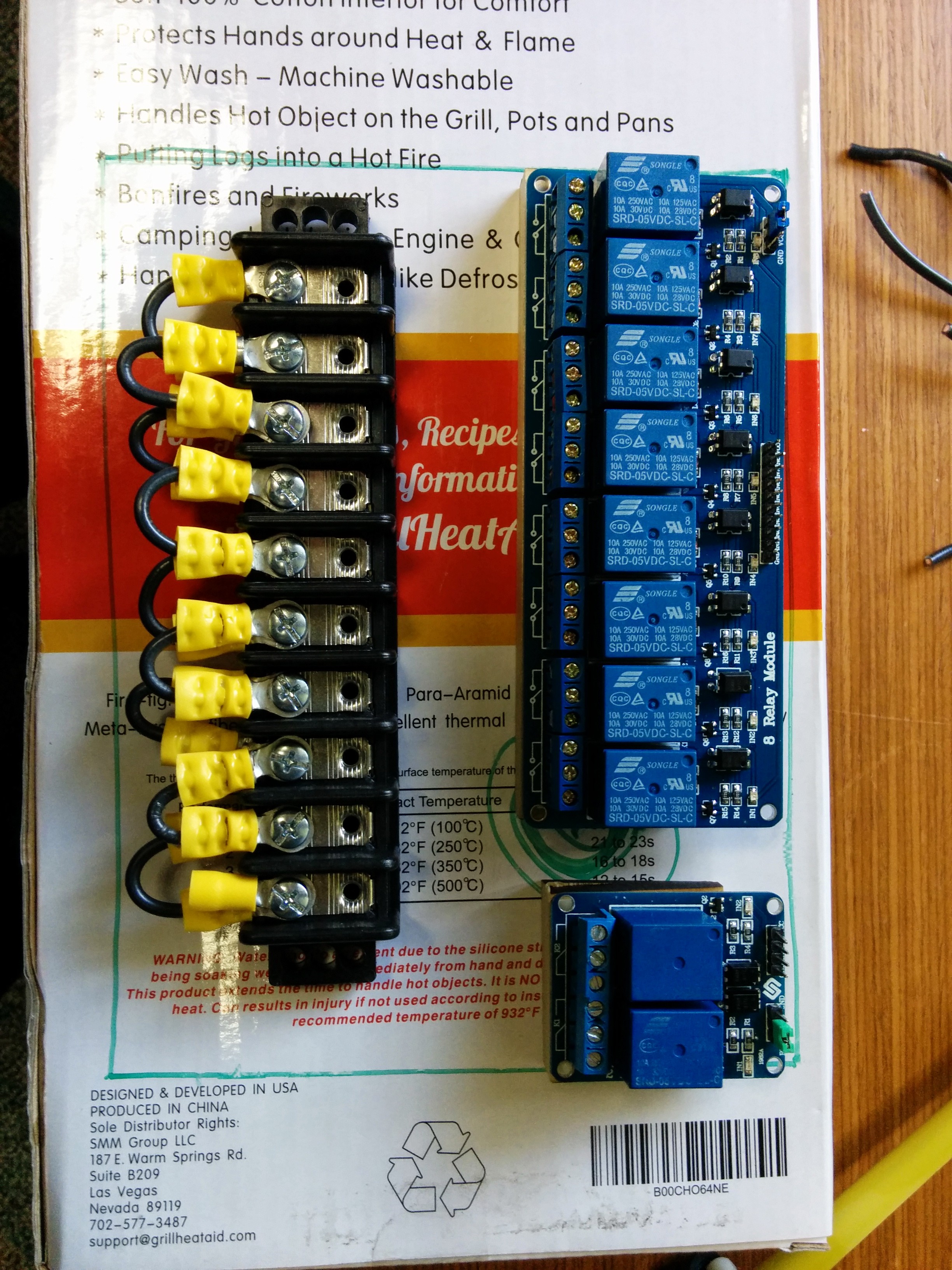
The next step was to hook it up to the relay boards! The 14 wires had to be ported through a hole in the clear protective guard then through one of the clamp connector holes in the metal junction box.
Control wires
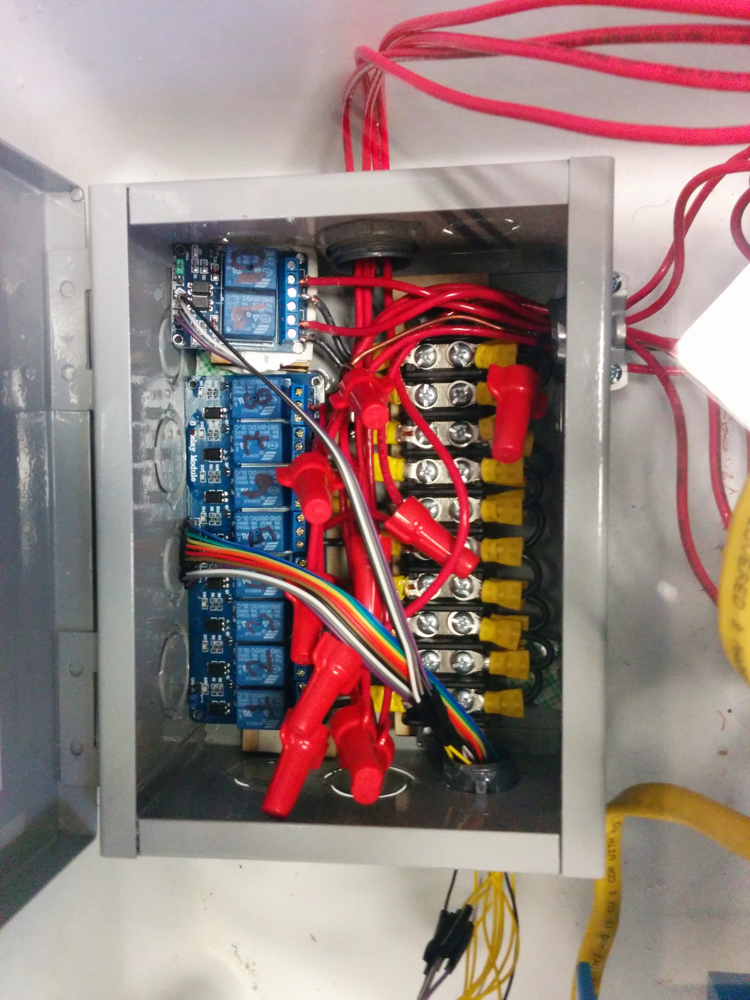
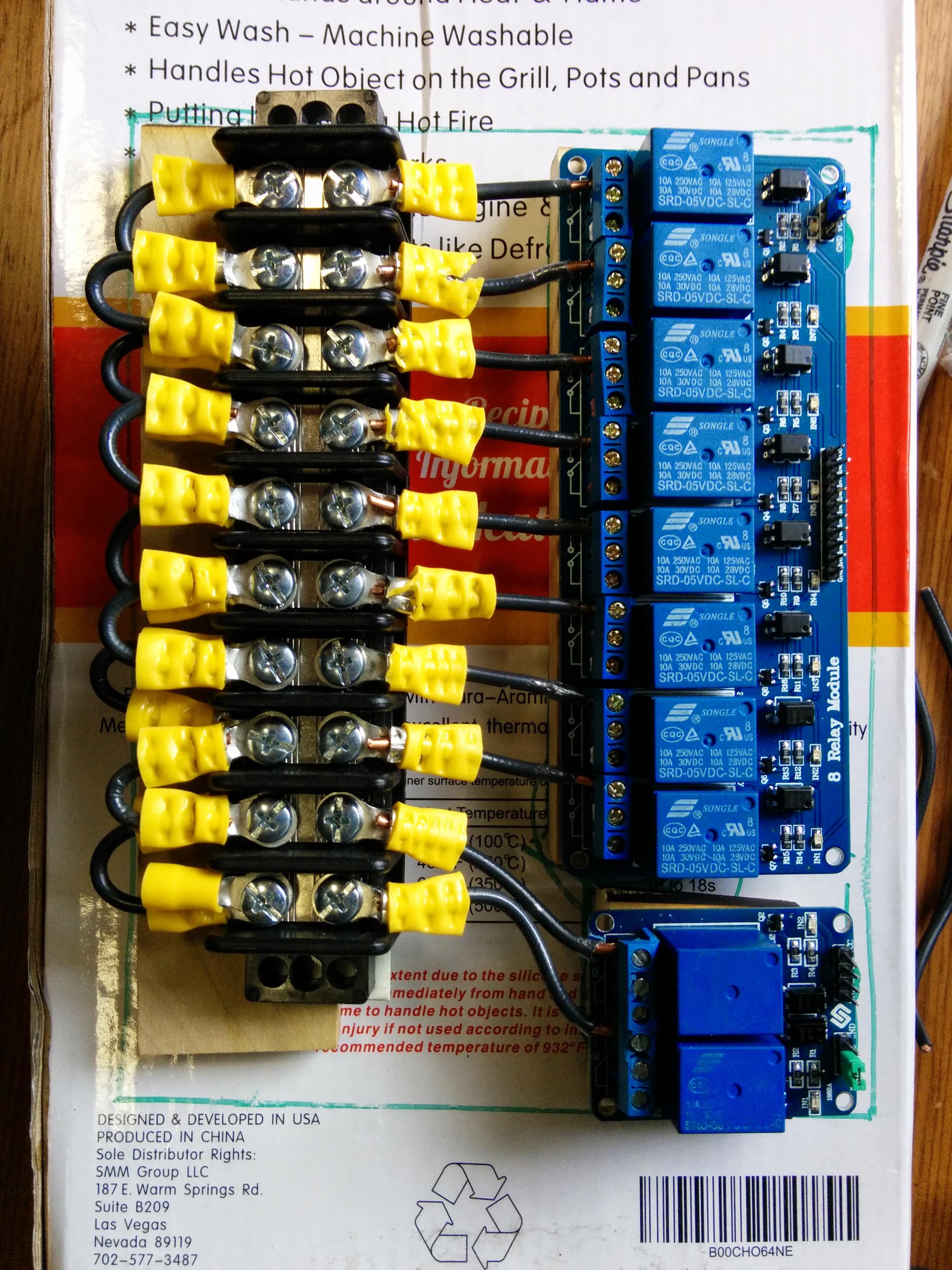
Once the control wires are in the metal box, they had to be carefully attached to the control, supply and ground pins of the 2 relay boards.
We have control!
Now that everything is wired up, it’s time to run some music and lights!
Here in the Freescale MakeIt Lab we ran a full light test:
https://www.youtube.com/watch?v=20Dsus8Gr4o
(Not shown: One of the ‘songs’ added was a music scale which was a perfect was to test out the lights!)
Stay Tuned for Part3, where we review the software and how easy it is for kids to program it!
So I was getting ready to write my next blog entry for the Magic Cooler, when….
Well, Esquilo!(squirrel in Portuguese) anyway!
The founders of Esquilo came to visit at work this week. They have a Kickstarter going on for their Esquilo Air board, a wifi-enabled development board targeted specifically to enable simple IoT (internet of things) setups to the Maker Community!
Freescale purchased some of the boards BEFORE the Kickstarter has ended and handed out to those intrepid folks willing to make it into something.
Pre-Kickstarter is cool.
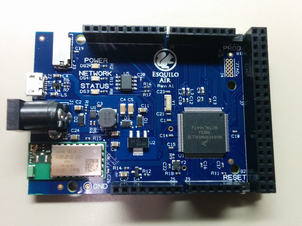
What is the Esquilo board you ask? Here it is:
Internet of Squirrel?
The “Air” board has Arduino-compatible pin headers, a micro SD card slot, and an awesome K64F FSL Kinetis micro with 1MB of flash! (not biased or anything).
Most importantly the board has built-in Wifi whose drivers have already been loaded on there. Everything is built-in on this board! Including the IDE! Plus it uses the Squirrel language, which is dynamic, so no compiling and loading!!
That’s right. From what I understand while not having yet played with it– is that the board having built-in Wifi capability lets you connect to it via your computer browser, like you would any router or access point. Then you write your code or load it in there. Then run it. No internet required. No USB required (unless you want for power). You can load code via the on-board micro-SD slot.
Very excited to see how this will work out and have many ideas for how I want to use it.
This project started out as something to help educate kids in learning to control Christmas lights with music using a microcontroller in an easy-to-use environment last year in the Makerspace for my son’s middle school. At that time, we used an Arduino Uno, but I was able to pretty easily convert to using the much more practical and powerful Teensy 3.1 thanks to the Teensyduino software add-on.
The most challenging part of that Makerspace music project was the AC circuit side of the hookup. To not modify the Christmas lights being controlled, I had to cut off the plugs on some sacrificial Christmas lights to serve as the controlled outlets.
I had since wanted to do a project upgrade, using regular AC duplex outlets to control many more lights! And fit it all into a portable, rugged “box” of some sort.
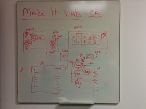
As with any project, I started off with some thoughts:
Initial concept drawing
A bit of circuit diagram in there.
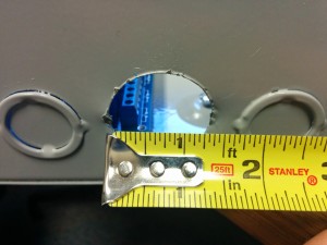
Initially, I had wanted to use a cheap, black toolbox to house the AC circuits. But after some measurements of the interior, it seemed a bit cramped for what I wanted to add, and the walls seemed too thin to support installing the ‘blue boxes’ needed to properly contain the AC outlets.
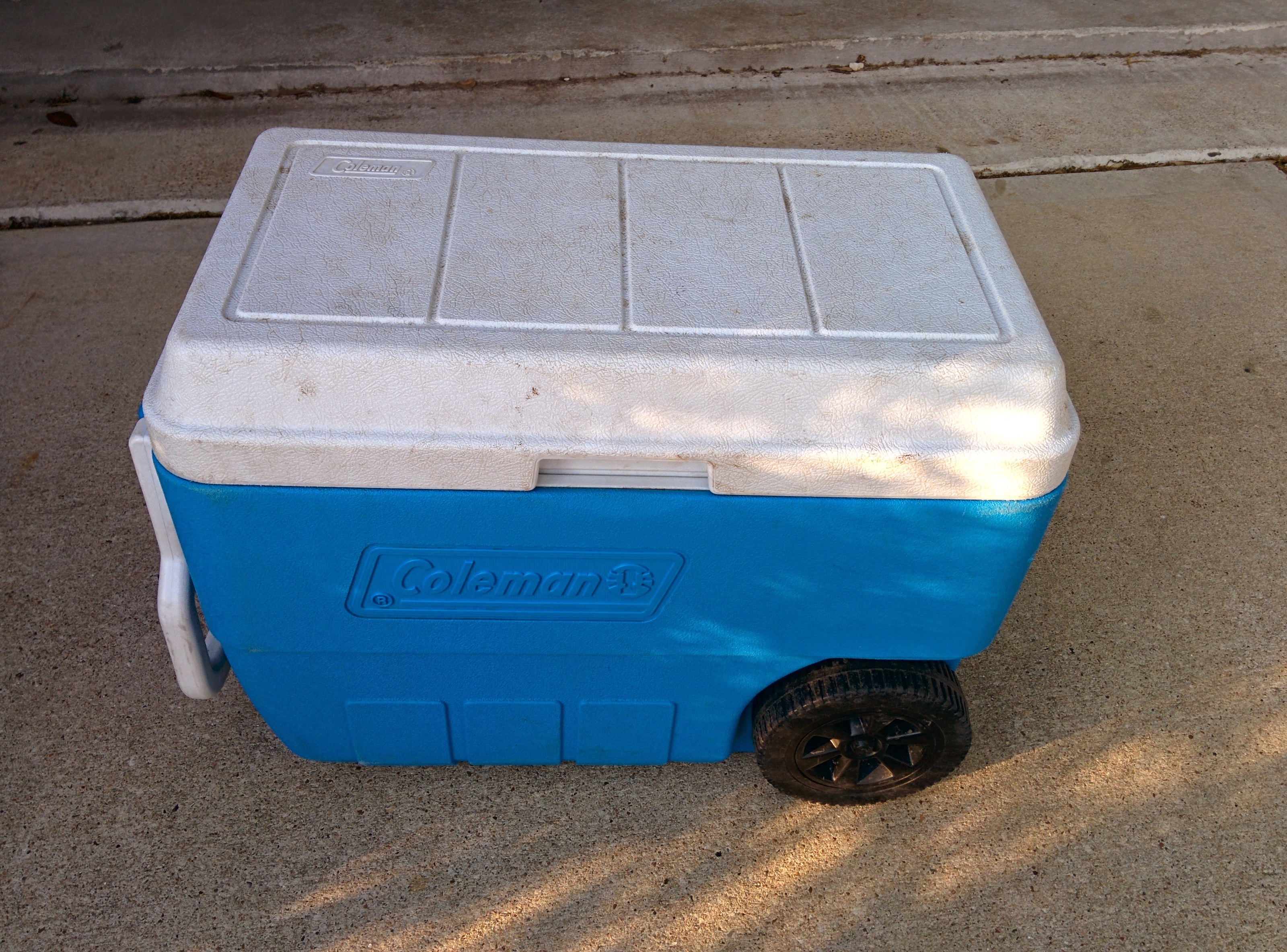
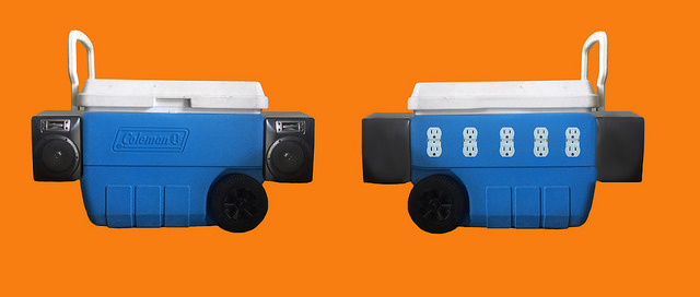
Fortuitously, I was cleaning out the garage around this time, taking stuff to Goodwill. As I was putting this blue Coleman cooler with broken lid hinges into the trunk of the car, it hit me that this would be the perfect container for a portable music and light show:
All kinds of possibilities!
It has 1″ thick walls, lots of room inside, a handle and wheels! The lid not being hinged on is actually a plus as it allows removing the lid completely to permit work inside.
Part 1 of this article will focus on the physical and AC electrical side of the build.
Electricity and Safety
I wanted first and foremost for the AC part to be as safe as possible. Just like in the walls in your house, what that means is containment of all connections via blue boxes and a master junction box. It also means having a circuit breaker or a ground-fault circuit interrupter. I chose the latter.
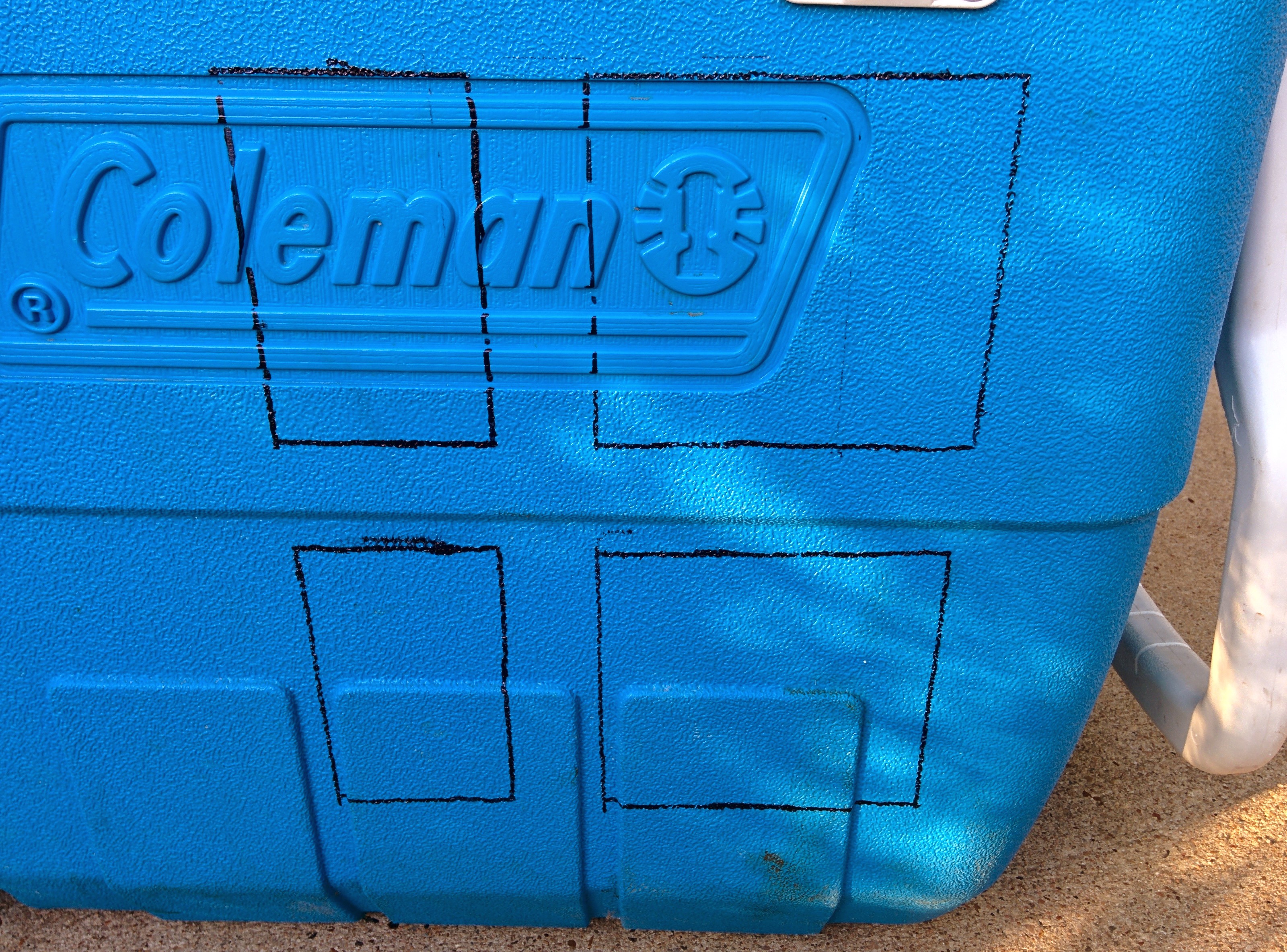
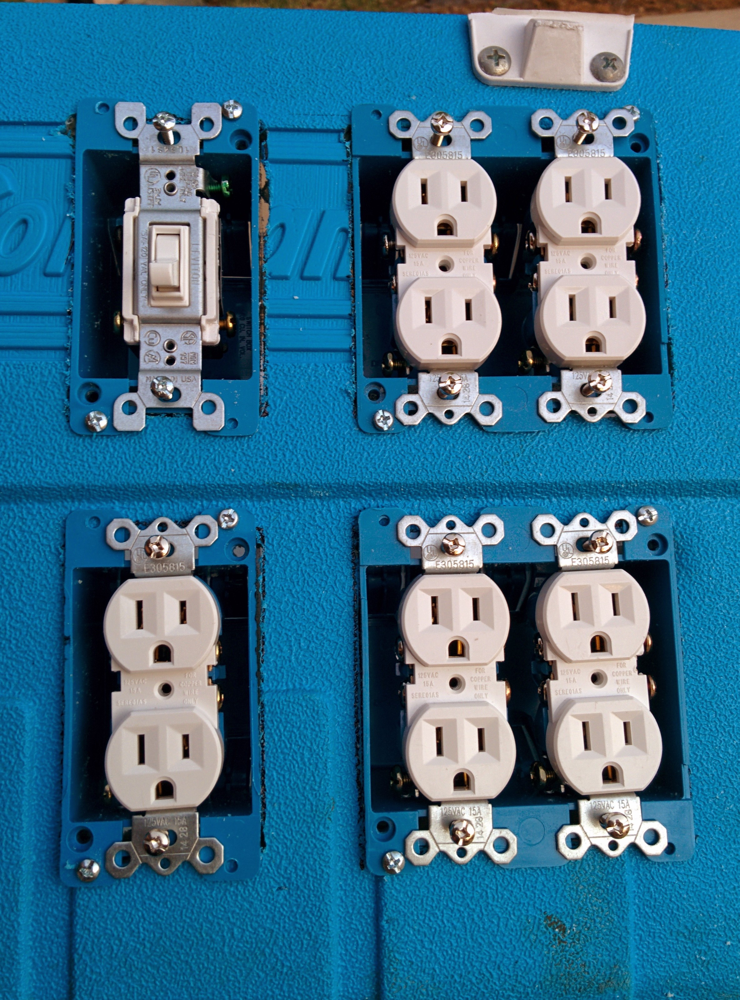
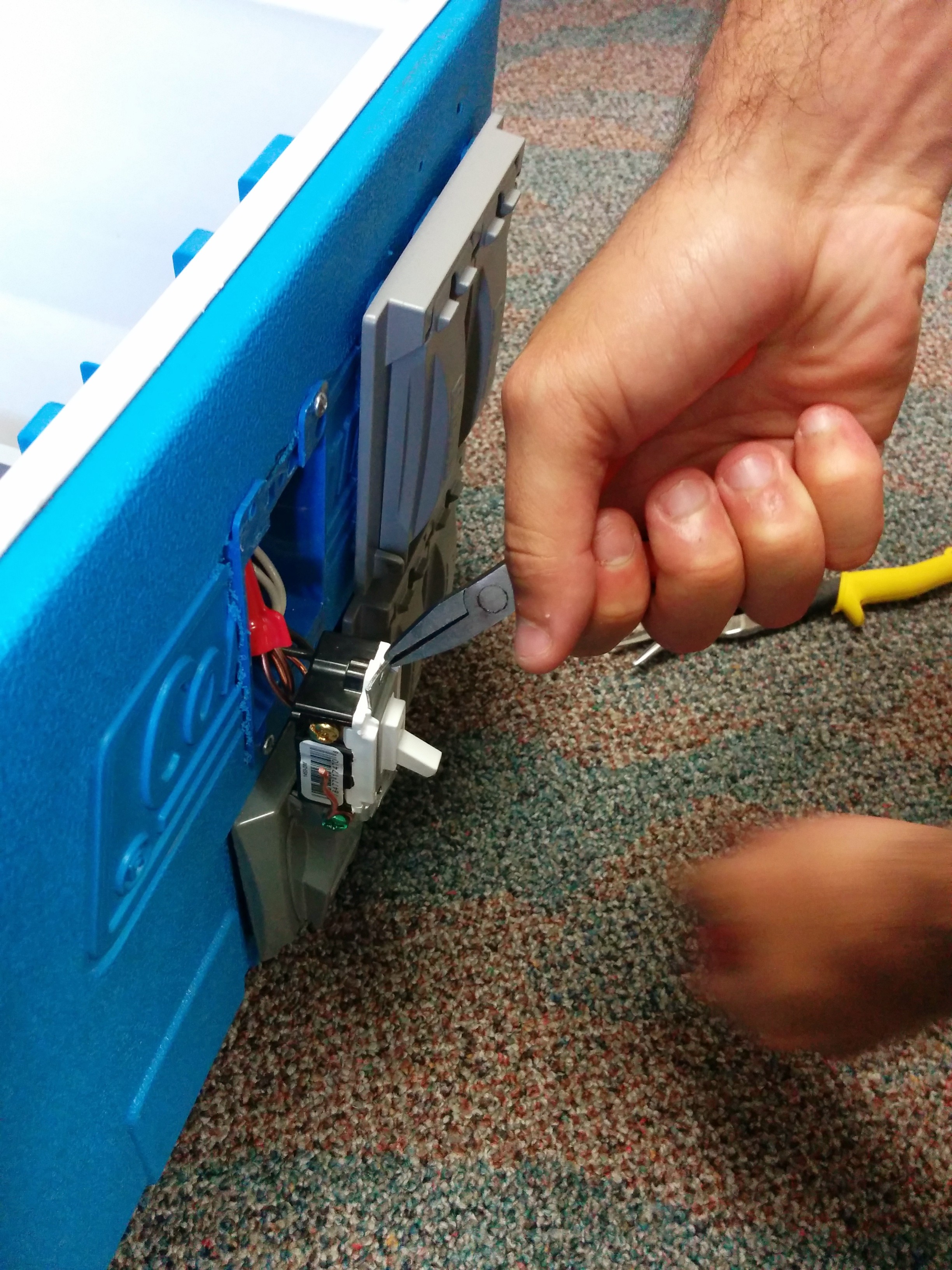
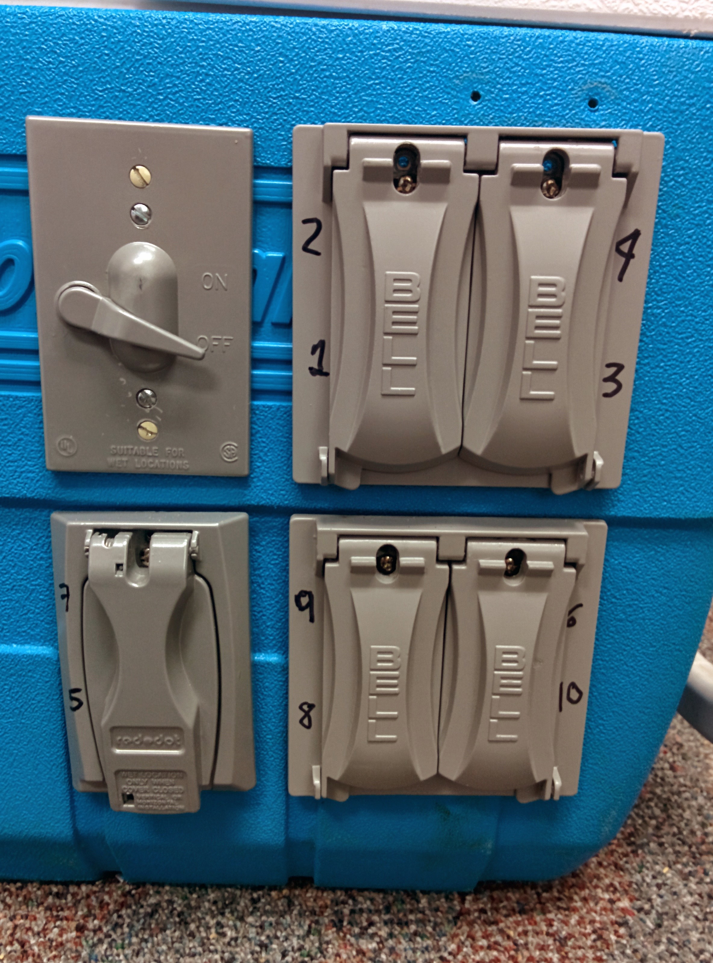
Step 1: Install the AC blue boxes and outlets in the sidewalls of the cooler.
I wanted to have 10 outlets total as I have 10 relays available for control, which means having 5 duplex outlets. I also wanted a simple light switch to help to turn off all exterior outlets if necessary, for safety reasons and to permit debugging code and music without having to worry about driving the external lights. The outlets were planned to be on the ‘back side’ of the cooler.
Out came the cutting tools…
Outline for blue boxes on Cooler back side.
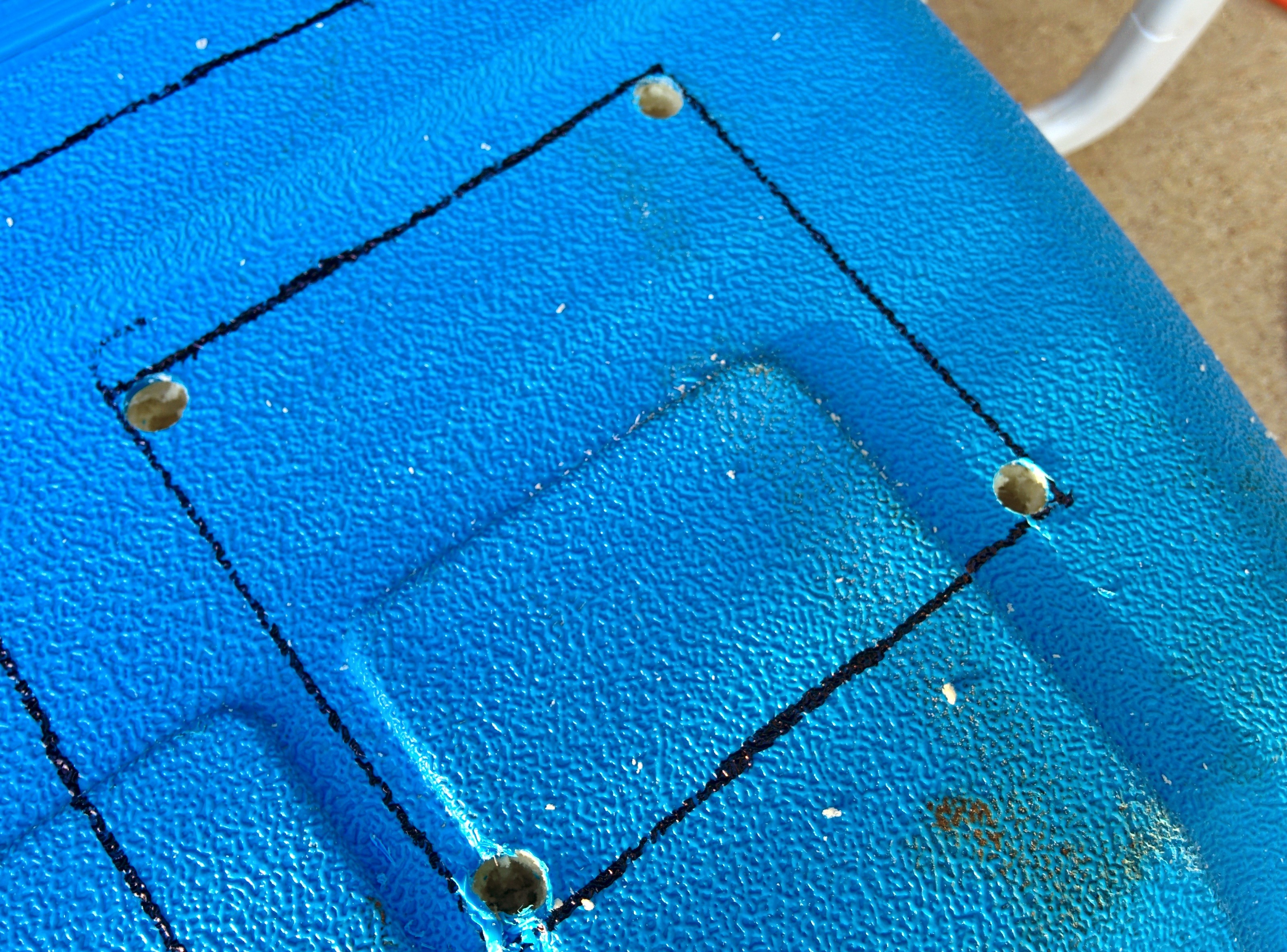
Holes drilled at the corners. Used a bit large enough to permit inserting jigsaw blade later.
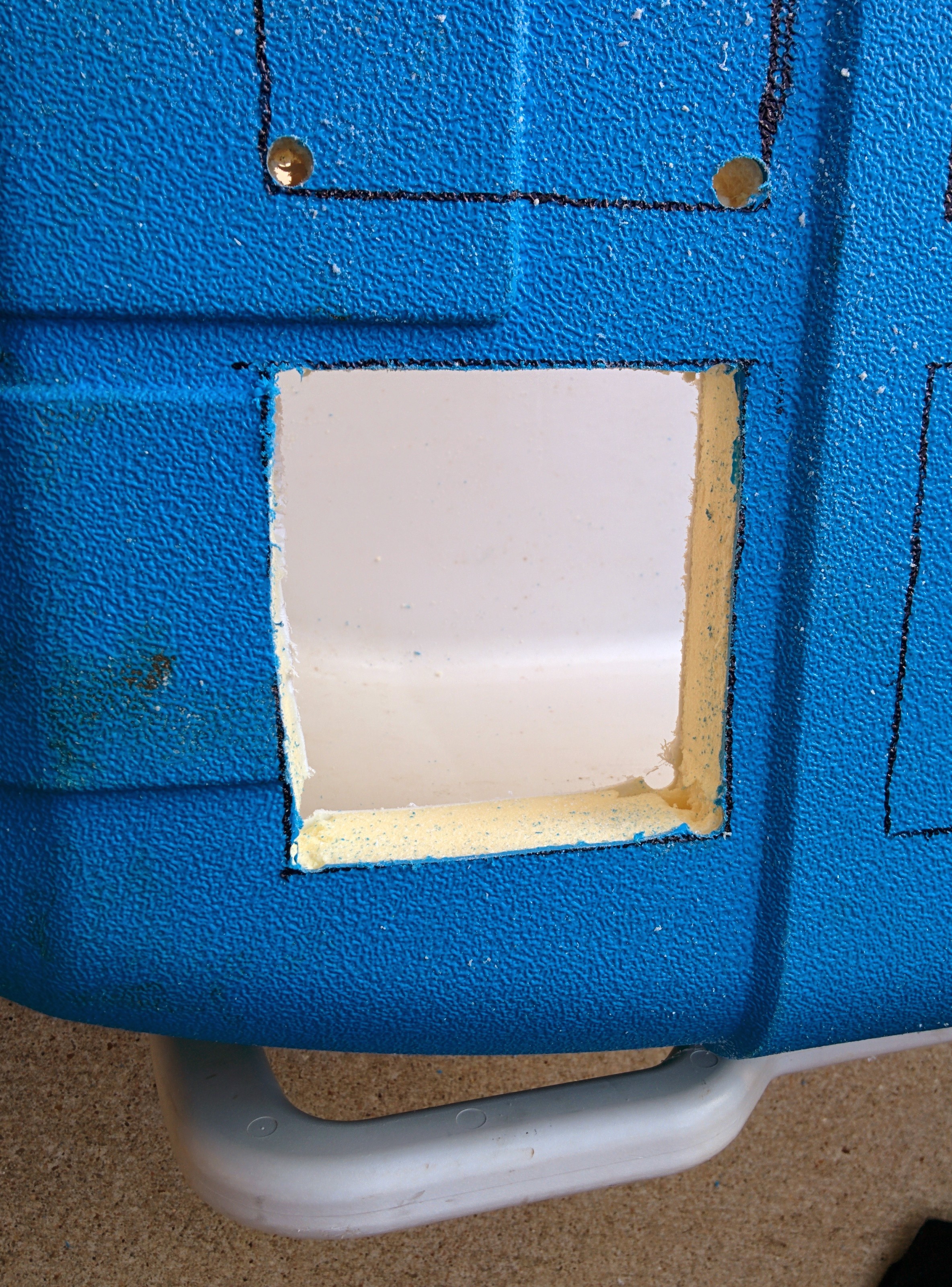
Used a jigsaw inserted into the corner holes to cut out the rectangles.
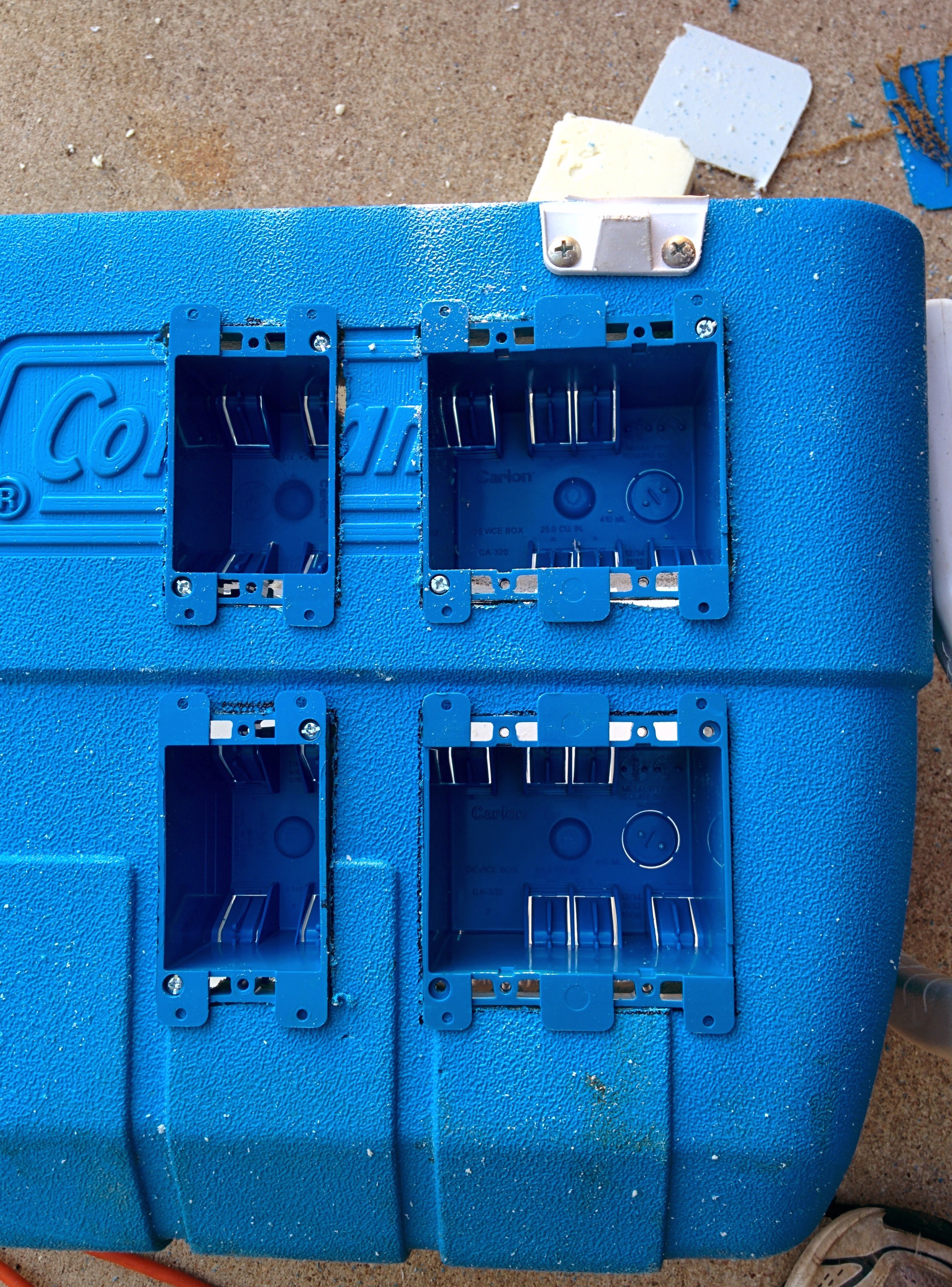
Screwed in the boxes.
Normally, in a house wall you’d want to attach these blue boxes to a stud behind the drywall. However, in this case the plastic exterior and interior of the cooler were tense enough to support the boxes.
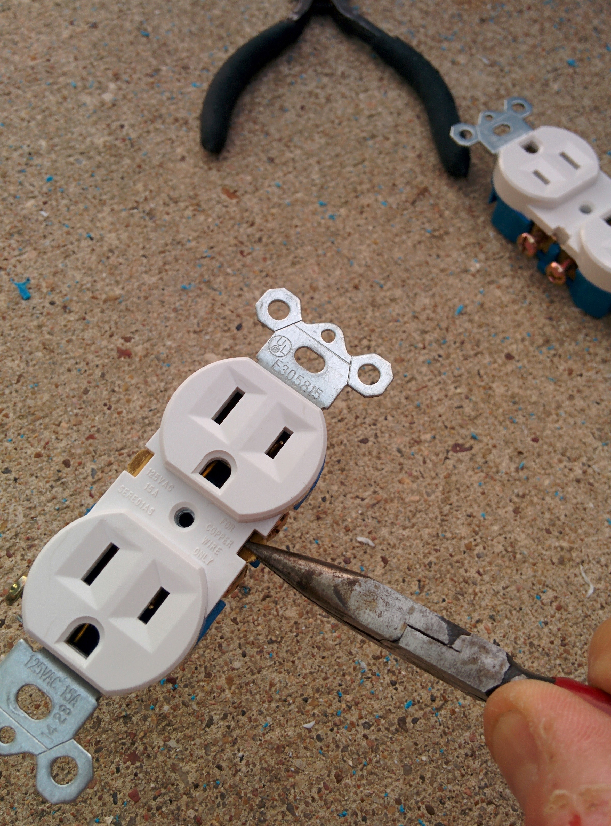
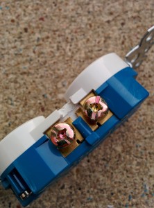
The next step was to loosely install the AC outlets to check the fit. I planned to remove them again later when doing the final wiring so here just installed them mainly as a placeholder. Prior to the install, since I wanted to individually control the outlets later, I went ahead and removed the tab connecting the hot sides together. I used pliers to wiggle the tab back and forth to break it off.
Removed hot side tab shorting the two outlets together.
Tab removed.
10 outlets and 1 switch added.
Wiring
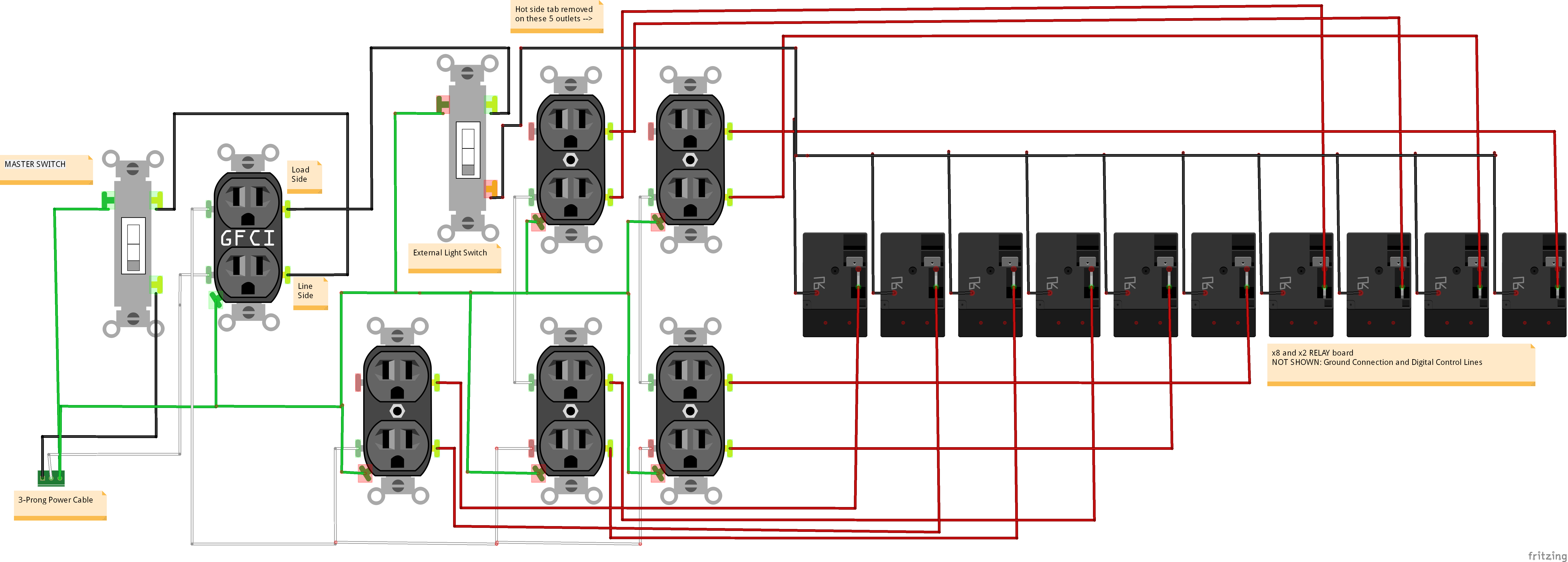
Step 2, wire up the AC circuit. Here’s a diagram showing the AC side of the circuit:
AC side of Magic Cooler Circuit
Basically, power comes in to the Cooler via a 3-prong wire (hot-neutral-ground) and goes through a master switch and a GFCI outlet which will be located inside a separate blue box inside the cooler and serves to protect the remaining outlets downstream. Let’s follow each line separately:
Ground (GREEN): Directly connects to every ground screw you can find. Not shown above is the ground connection to the metal junction box housing the 10 relays.
Neutral (White): Connects to LINE side of GFCI outlet– comes out of LOAD side of the GFCI receptacle and connects to the Neutral connector of every downstream outlet.
Black (Hot): Connects to LINE side of GFCI outlet– comes out of LOAD side of the GFCI receptable and connects to the secondary Light Switch. Hot leaves this light switch and connects via a bus terminal to the Normally Open side of each of the 10 relays.
Red (Switched Hot): Connect from the common terminal of each of the 10 relays to the Hot screw for each of the 10 switched outlets.
I used #12 Romex to do the wiring, although I probably should have used something smaller gauge for the short runs here as #12 is difficult to work with (hard to bend), but at least now I know the circuit is very robust.
Main blue box wiring done.
I ran the 3-wire Romex box to box just as is done in a house wall. However, after the first set of duplex outlets the hot (black) wire was removed from the Romex bundle and brought down to where the future junction box would be. Red wires were connected to the hot side of each of the 10 outlets and also run down to where the junction box would eventually be.
I decided that the GFCI receptacle and master switch should be located inside the cooler. The GFCI provides some protection from accidental touching, wires coming loose creating shorts, and would help if I ever planned to take the Cooler outside. It would also serve as a standard outlet to power the microcontroller board and other accessories.
Since the Cooler already had a nice, convenient drain hole, I decided to use that to run the main power cord. I cut the power cable from a 10-outlet power strip so was confident it had sufficient current-carrying capacity. A knot was added to prevent from accidental tugs on the power cord from damaging the internal wiring.
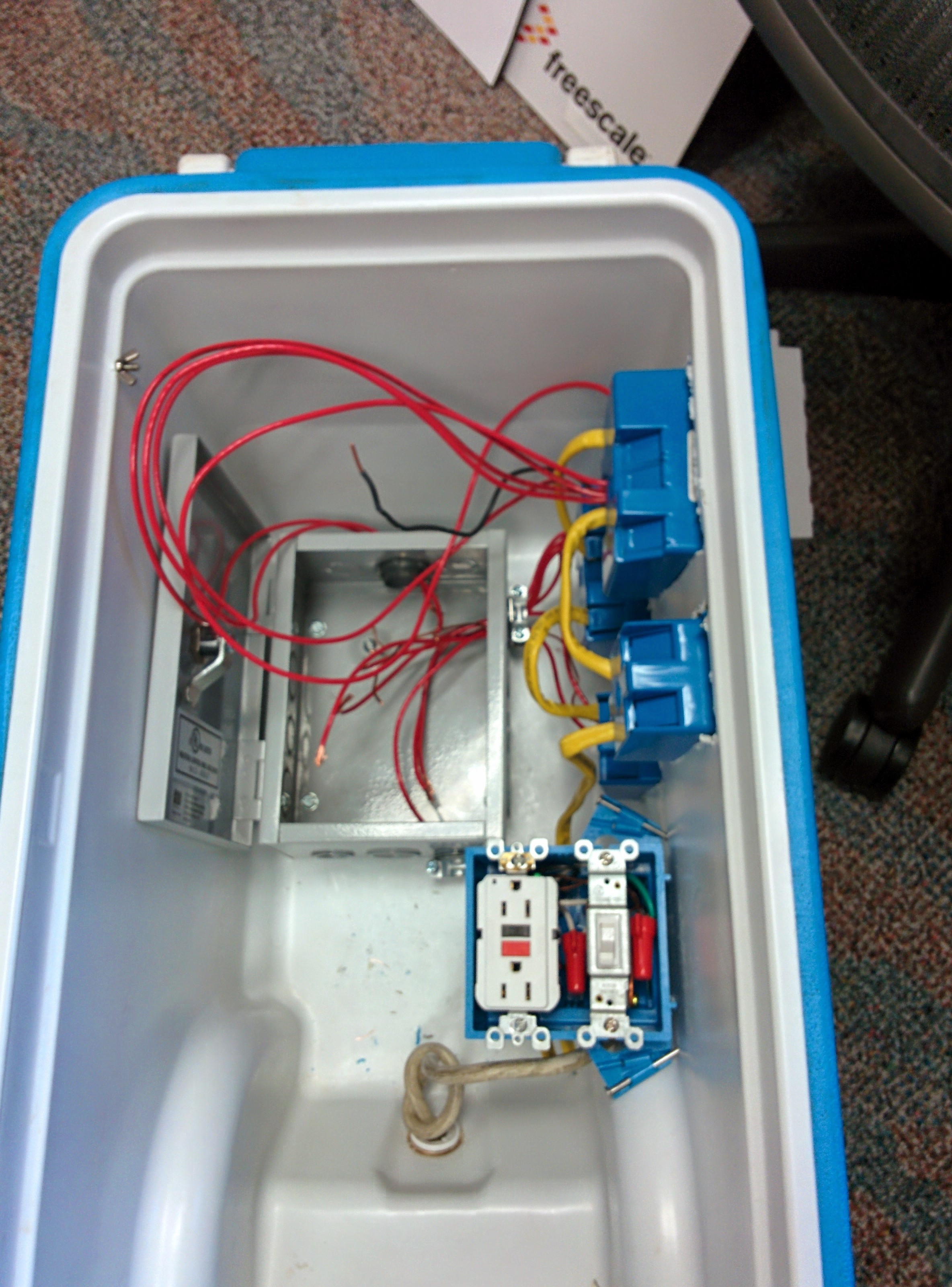
Next step, the junction box.
Junction Box Prep
The junction box was used to house the bus terminal to expand the single hot (black) wire to the 10 relays and the connection of those relays back to the switched outlets (red wire). In case of any electrical fire or loose wire, the box would serve as containment and/or ground.
Some electrical stuff is just cheaper to get on Ebay than at your local hardware store, so I found a really nice and strong junction box on Ebay that was the perfect size.
Metal Junction box off Ebay
Next, I had to pop out the 1″ and 3/4″ holes in the box (not easy!) in order to permit inserting cable clamp connectors. These served to hold any wires going into and out of the box and prevent them from rubbing against the edge of the metal hole.
Next, I screwed the box to the bottom of the cooler to hold it in place. I made the junction box door open to the side opposite the blue boxes, to permit easy access.
Junction box mounted to the cooler.
Then, I connected the ground line to the ground screw of the box itself. Double-stick tape was then added above each of the mounting screws to prevent shorting anything inside to ground inadvertently.
Box screwed down to cooler bottom with tape above each screw. Note the ground wire connected to the box.
Junction Box Wiring
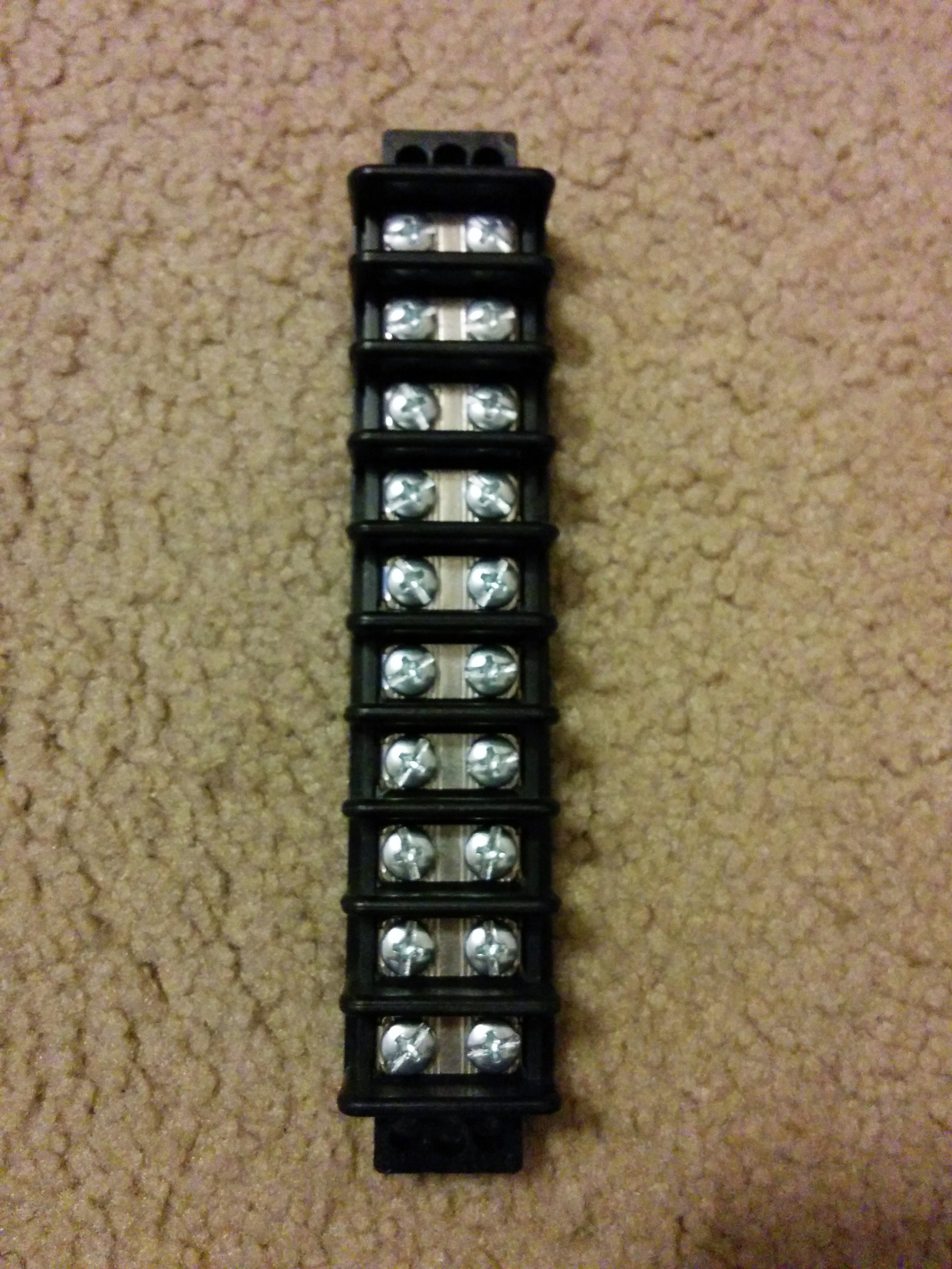
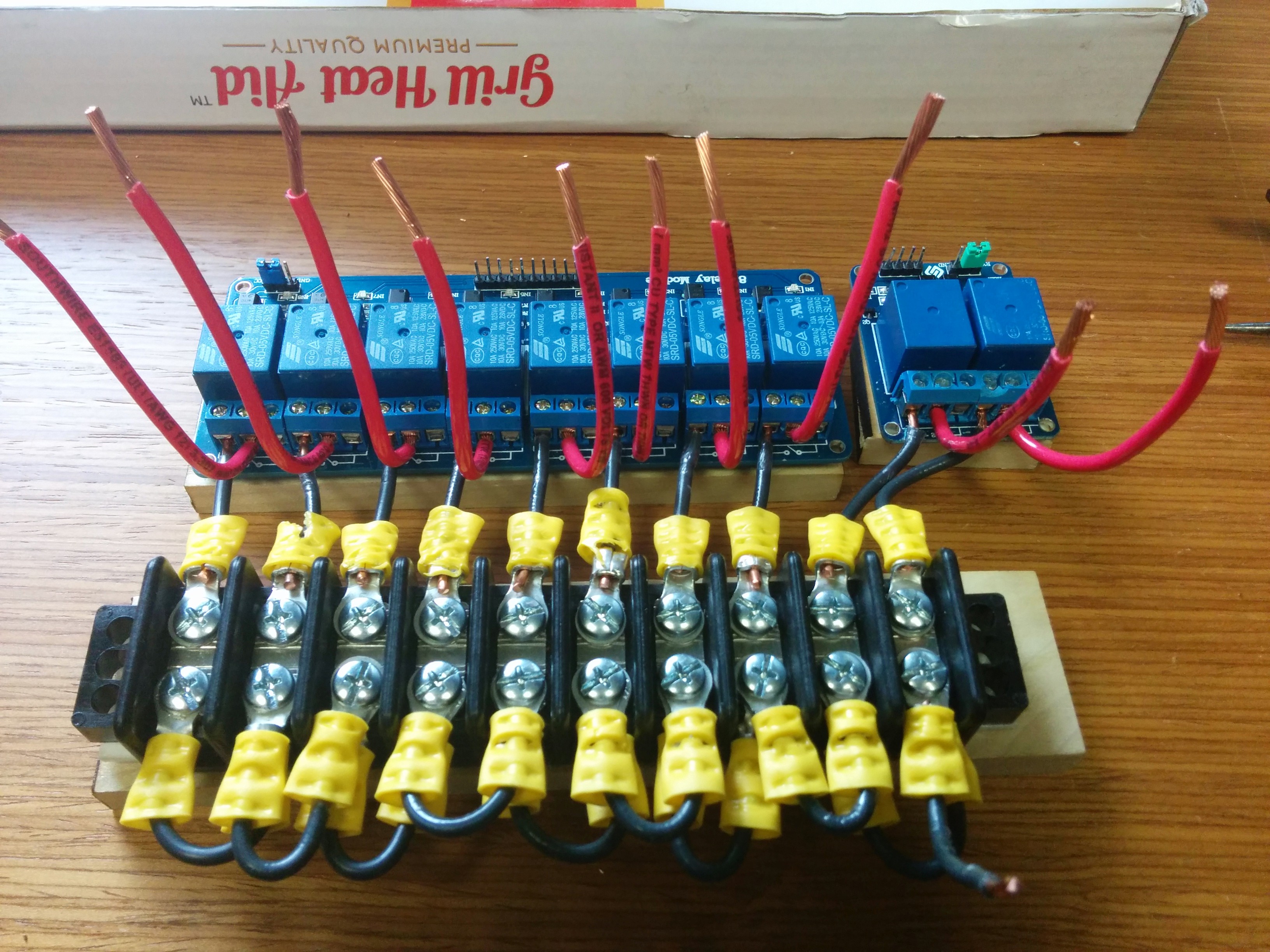
This was probably the trickiest part of the entire build: Wiring up the relays and the bus terminal block and mounting them inside the junction box IN THE BOTTOM OF A COOLER.
Basically a bus terminal block is just a way to connect heavy gauge wire together:
bus terminal block
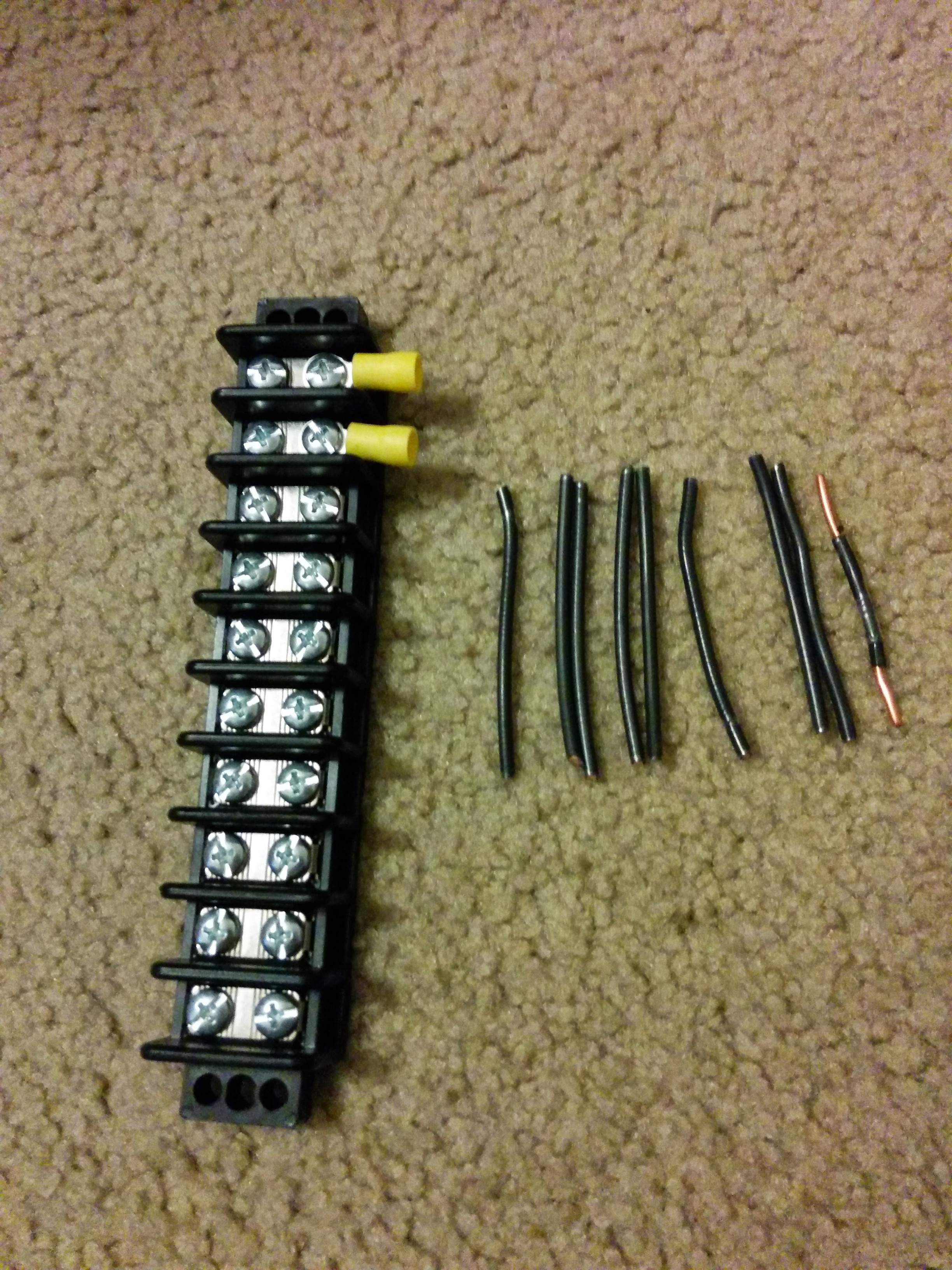
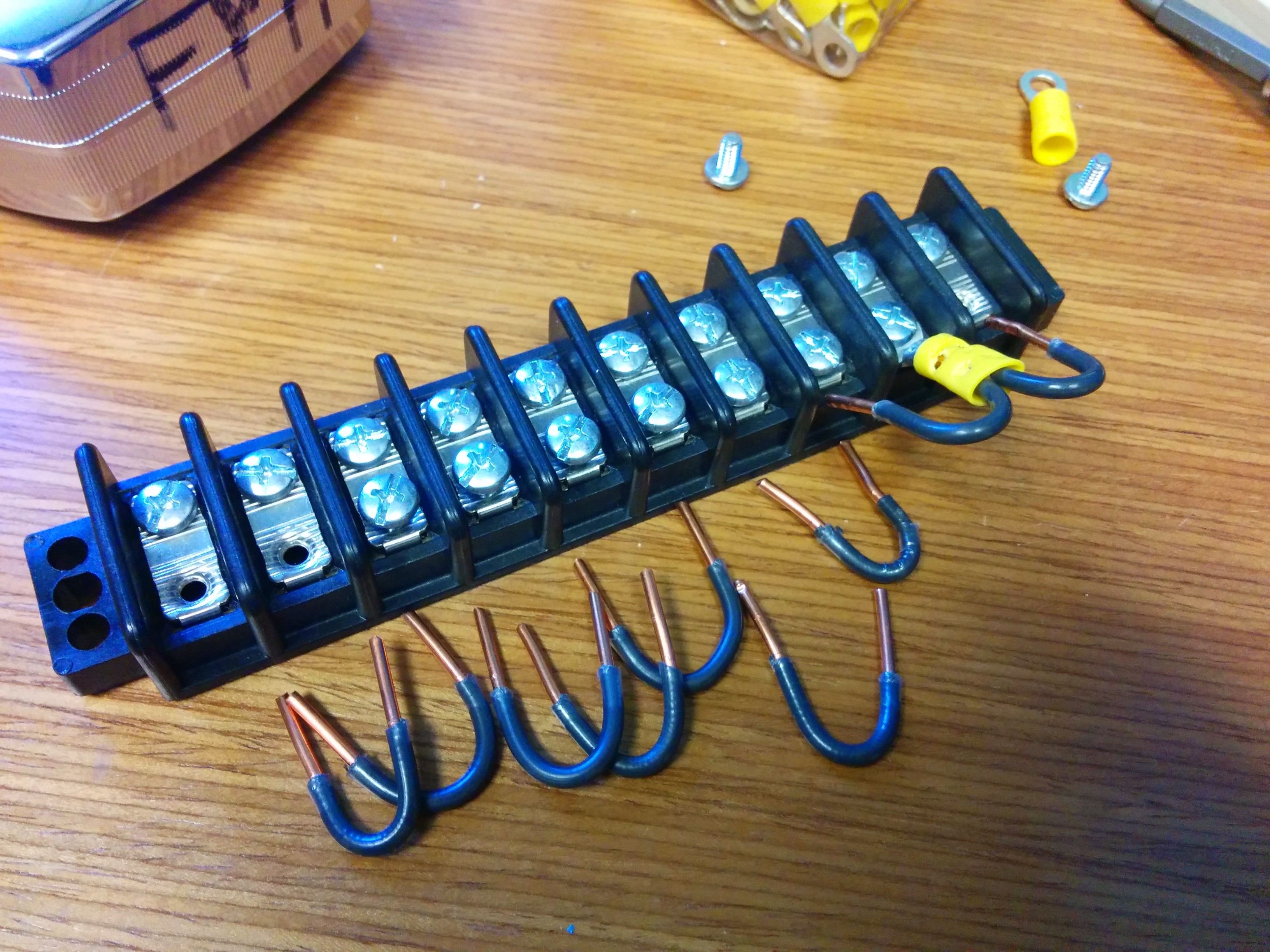
By using short U-shaped pieces of the hot (black) wire and ring terminal connectors, I was able to use the bus terminal block to help connect the line hot wire to the Normally Open (NO) side of the 10 relays.
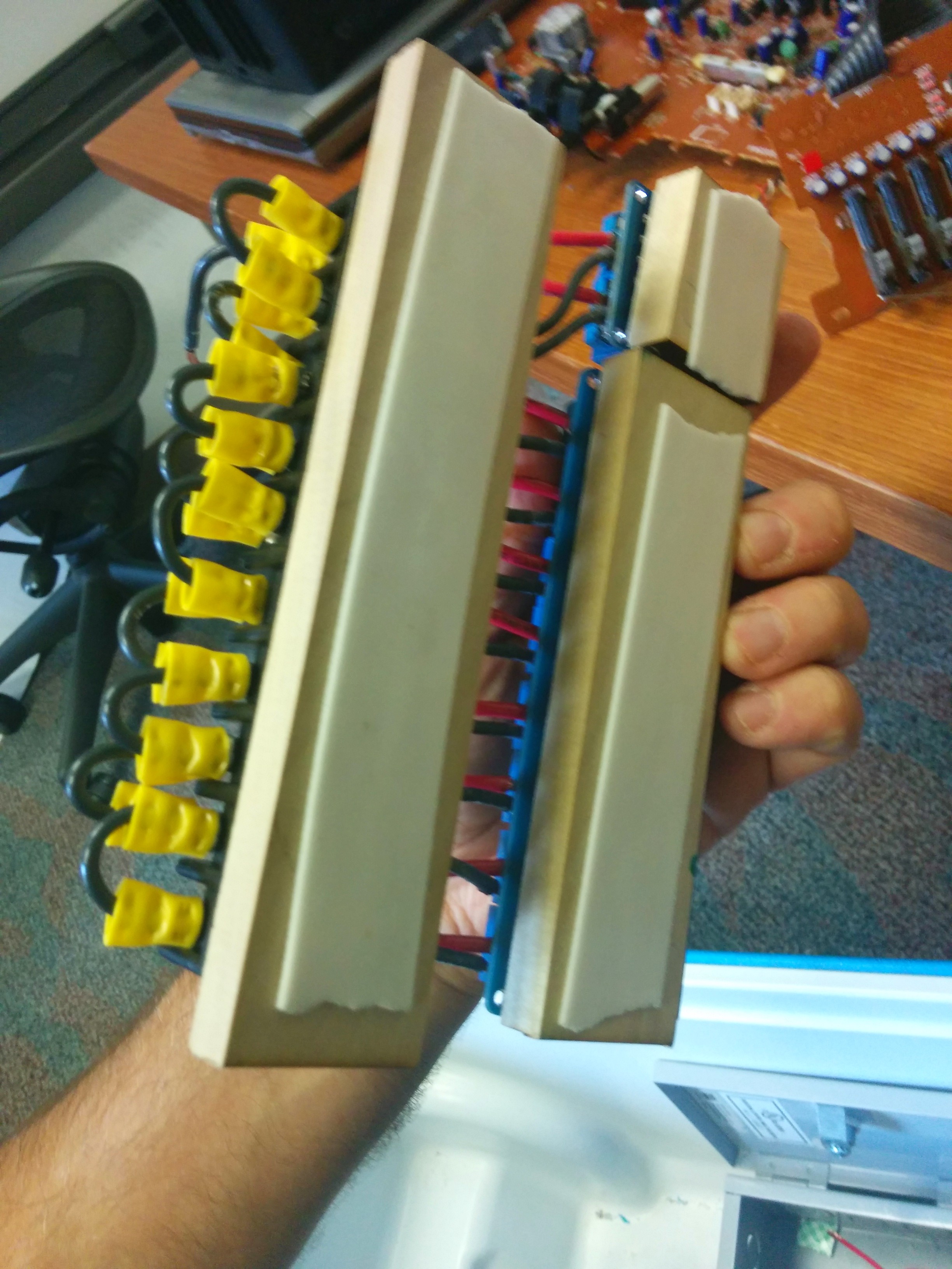
Given the fact that I had already mounted the junction box into the cooler, I made a template out of a old box that had the same dimensions of the interior of the box to permit doing most of the the wiring in a more comfortable way.
Green line here is the limits of the inside of the junction box.
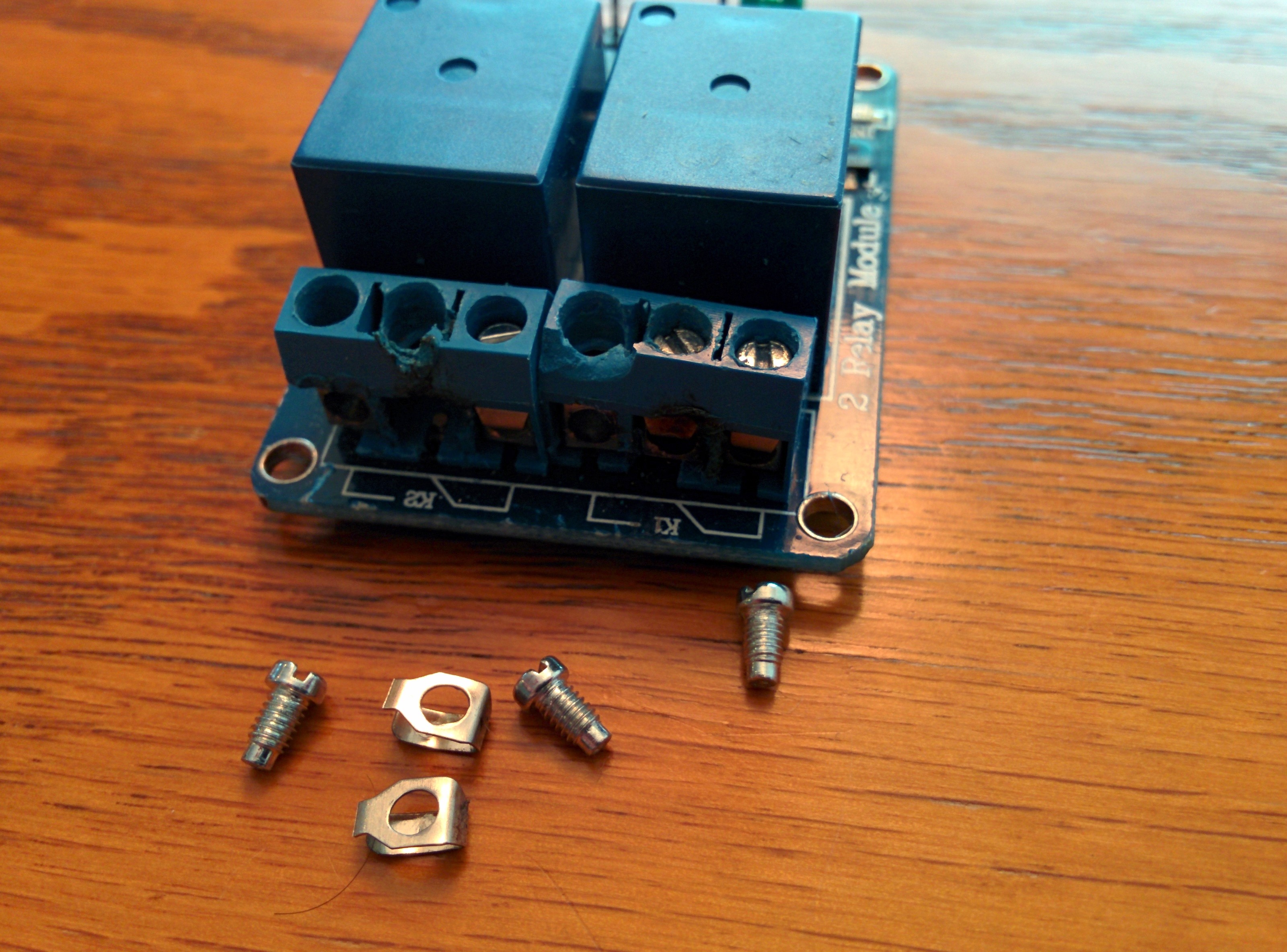
It was a good thing too that I didn’t have a single x10 relay board– as the junction box has a big bump around the ground screw. So the break between the x2 and x8 relay boards helped to accommodate this bump.
Each of these placed on a block of wood to provide stability and isolation from ground.
Given that #12 Romex is very stiff, this was the best way to ensure that the final assembly would in fact fit into the box. Although, if I had to do it over again, I would probably have used a smaller gauge wire, as with #12 it was very difficult to interface with the relay terminal blocks. I had to ‘encourage’ them to connect.
Get in there…
What happens when you force 12-gauge Romex into relay terminal block. This board had to be replaced.
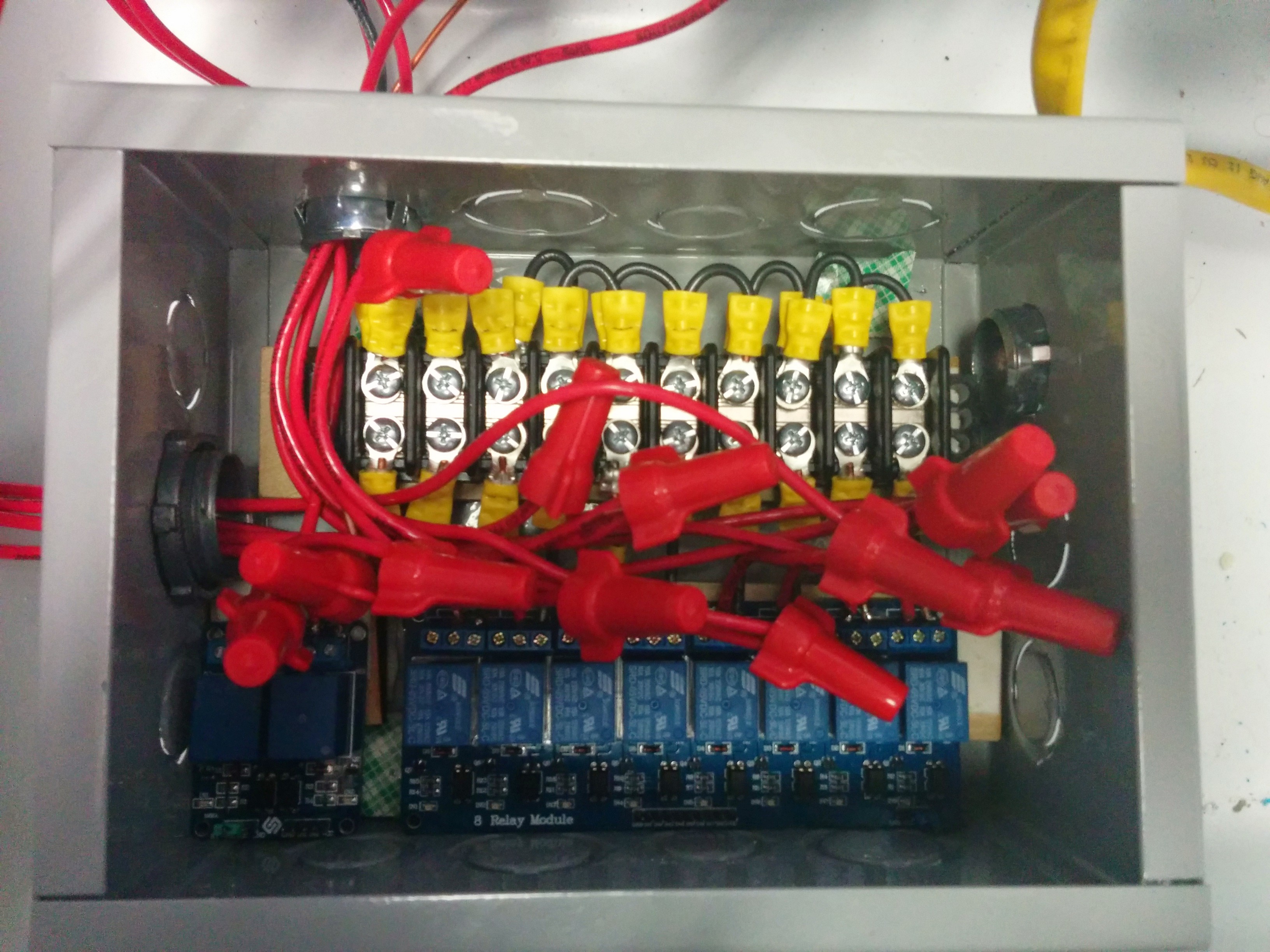
Finally done!
Double-sided tape added!
By the way, color coding when working with AC circuits is VERY important: Black connects to black, red to red, ground to ground.
Perfect fit!
Not bad!
Enclosing
Now that the AC wiring was done, the next step was to enclose all AC circuitry to prevent accidental mishaps.
(Well, in reality the next step was testing all the connections with an ohmmeter, of course without connecting the AC! This should be done at ALL stages of the AC wiring).
To enclose the exterior outlets and light switch, we decided to add weatherproof covers. These were readily available at the hardware store.
Andres clipping excess metal to add the switch cover.
Outlet and switch covers added
Note that we still need to caulk the gap (like you would at your house) around these enclosures if we truly want the Cooler to be waterproof. The covers were numbered with which relay they were connected. I cared more about the relay order being numbered sequentially than the outlets.
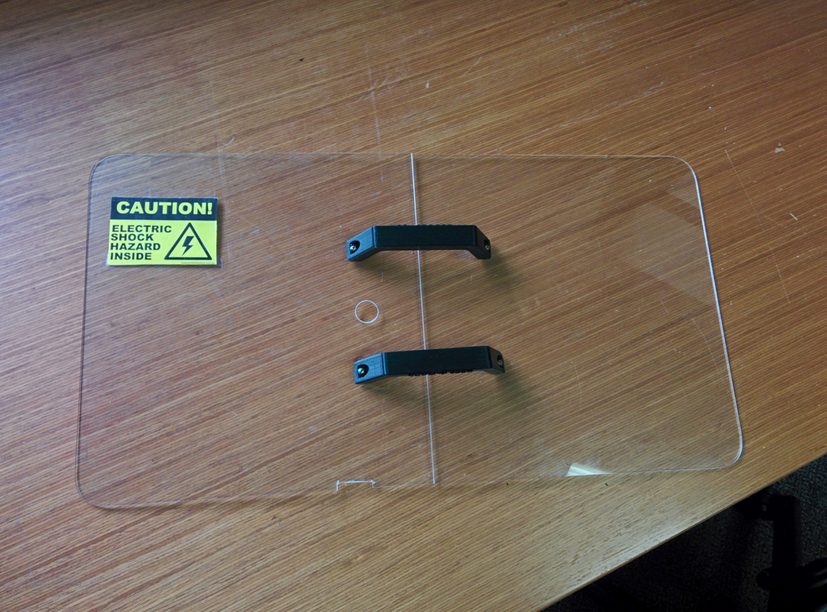
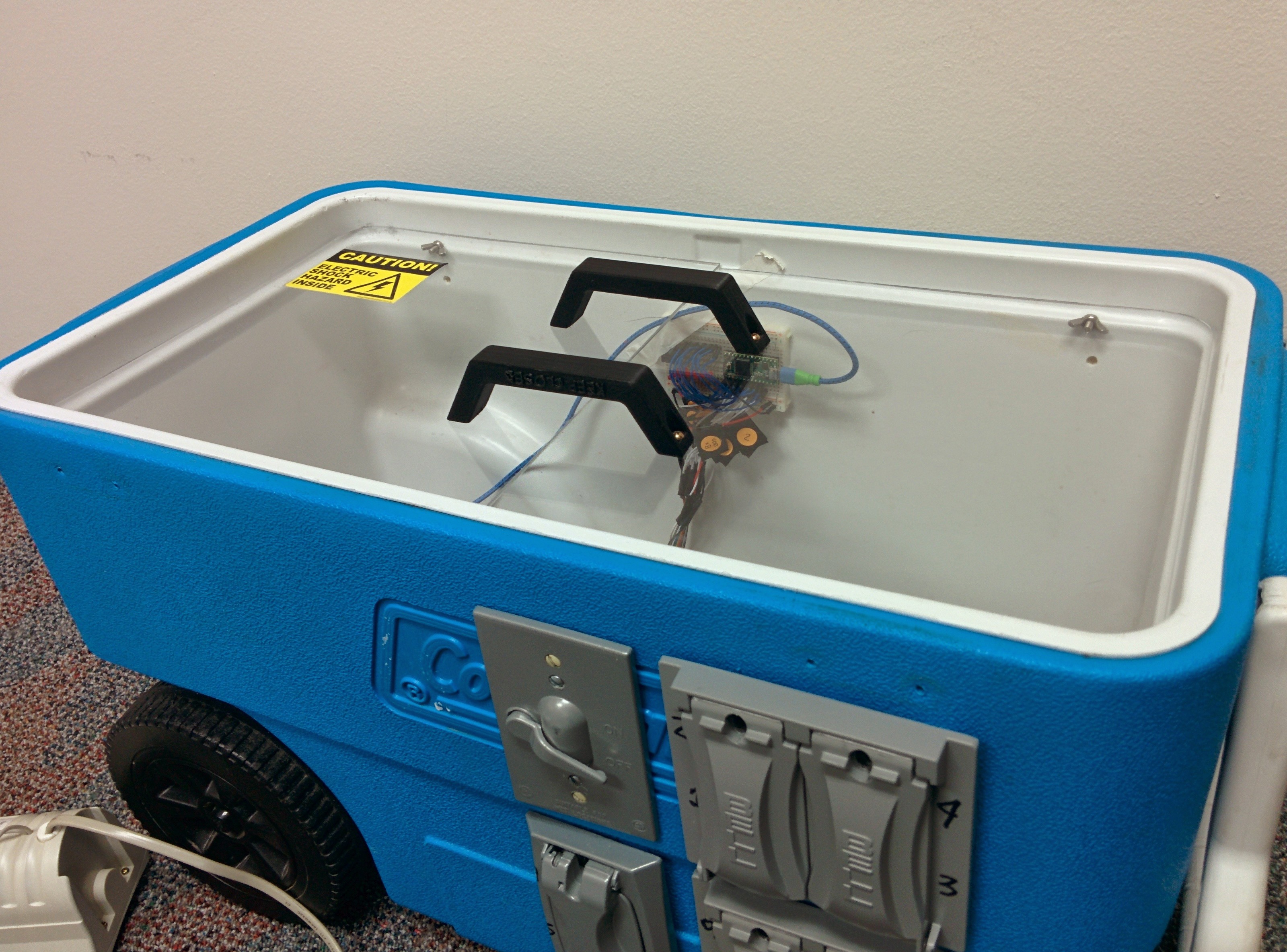
The next step for safety was to enclose the entire interior of the cooler with an acrylic “lid”, so the curious could still view the interior, but do so safely. The idea was that all AC circuitry would be below the lid, and all DC or microelectronics and prototyping related stuff would be sitting on the lid like a shelf.
The cooler provides a nice lip around the top of the inside where the lid/shelf fits and since it’s very thin doesn’t interfere with placing the Cooler top/lid in place. The Cooler lid actually has a large interior as well so you can still fit several inches worth of stuff on the acrylic lid/shelf.
In order to fit the hole exactly, we used a laser cutter to round off the corners. Cardboard test pieces (not shown) were put into the laser cutter until we got the corner exactly right then the same design was reused on the acrylic. Due to limitations of the interior of the laser cutter, we had to use two separate pieces of acrylic.
To join the two parts of the lid together, two handles were 3-d printed and attached. Holes were then added where control and other wiring between the AC and DC parts of the system would go. A notch was added to one side for the power plug for Computer speakers that would be doing the sound.
Safety lid
Finally, a warning sticker was added to indicate the dangerous nature of what was beneath.
Safety lid with warning
Safety lid in place in Cooler.
Now we just needed to hook up the microcontroller to the relays to control the lights, and to the speakers to make sound!
Andres, Nikki and I at Freescale have submitted an entry for the Austin Mini Maker Faire 2015 based on the Music and Lights project exhibited here! Of course it since has been converted from using Atmel-based Arduino to using Freescale (Kinetis) based Teensy 3.1 !!
The above is a mockup of what it could look like. The objective is to control up to 10 sets of lights and play music.
After a bit of a scramble late last week, we were able to get v1.0 of the Makerspace sign up at my sons’ middle school Friday morning!
This is the conclusion to the project I mentioned before (Music and Lights), where an Arduino was used to drive a small speaker and some LEDs. My initial code was done to play Imperial March (from Star Wars) and Super Mario Bros Overworld Theme. But the kids would hopefully take it from there and make it their own.
It’s Time to Play the Music…
One of the kids with his dad’s help was able to extend my code to include many more measures of Jingle Bell Rock. The Arduino code, written in C, was written in a way to make it easy to play any song (single tone at a time). For example, the first line of the tune:
Looks like this in the code:
// Jingle Bell Rock
int bpm = 120;
int song[100][2] = {
   {R,Q},{C6,E},{AA5,E},{B5,E},{AA5,E},{G5,Q},{C6,Q},{Bb5,Q},{B5,Q},{R,Q},
      {C6,E},{C6,E},{C6,Q},{B5,E},{B5,E},{B5,Q},
Basically it’s a 2-dimensional array where the entire song is in braces { } where each ‘note’ is a pair of values indicating the note/tone and duration. Given that it’s single tone music, generally you want to hit only the highest note for each beat to play out the tune.
There are 8.5 octaves of notes available, starting with the lowest at C0 going up through C1, C2, … C7, to the highest at C8.
All 12 pitches of the chromatic scale are represented as follows:
Where x represents the octave. NOTE: Lowest note is C0, highest is Eb8.
Note also that the A is represented here by ‘AA’ since A0, A1, etc. are reserved terms in Arduino code-land (represent names of external pins).
A rest is represented by an R (no sound).
Note durations are represented with the following symbols:
W = whole note
H = half note
Q = quarter note
E = Eighth note
S = Sixteenth
You can represent any other fractions of time simply by writing as an equation in the code, e.g. {C6, Q+E}.
It’s Time to Light the Lights…
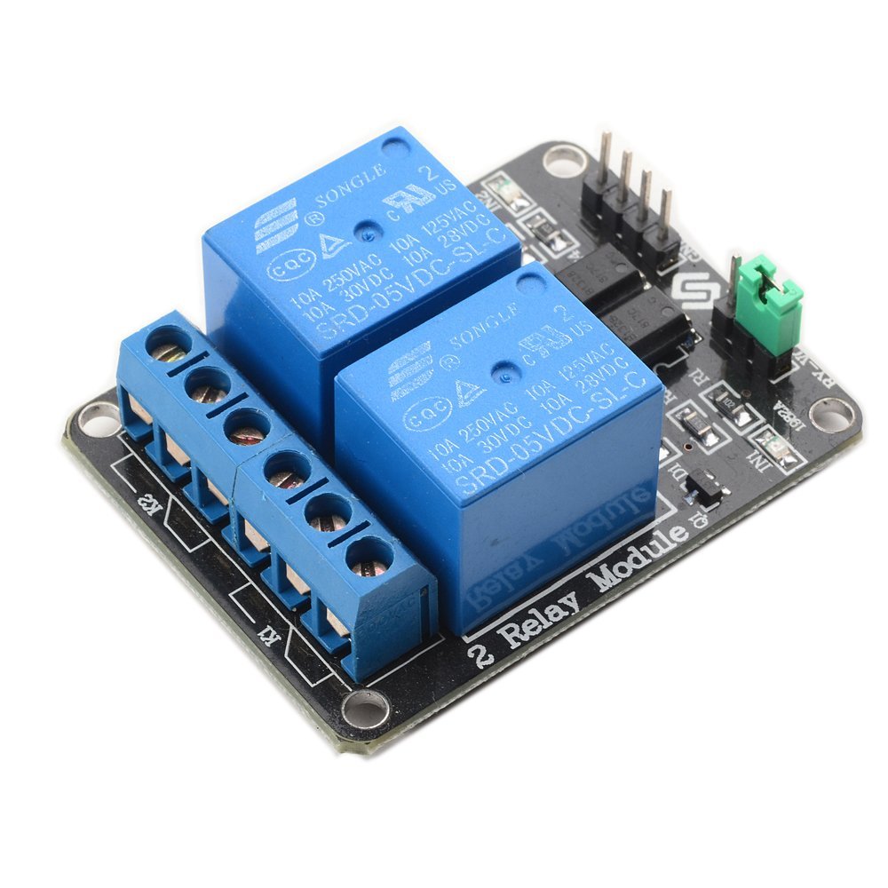
Now that we had a tune, we had to decide what our light show would look like. We had wanted to use Christmas lights controlled by the Arduino. I decided for simplicity to use an off the shelf relay board (SunFounder 2 channel 5V relay shield) that could be driven by the 5V Digital I/Os.
Generally you can use a relay to help you control something high-power or high-voltage like 120V AC electricity with low-voltage, low-power electronics. Relays have been used in everything from cars to sprinkler systems, having started out from the telegraph.
We decided in the end for simplicity to use 2 sets of lights alternatively blinking for our ‘light show’. This made my job that much easier.
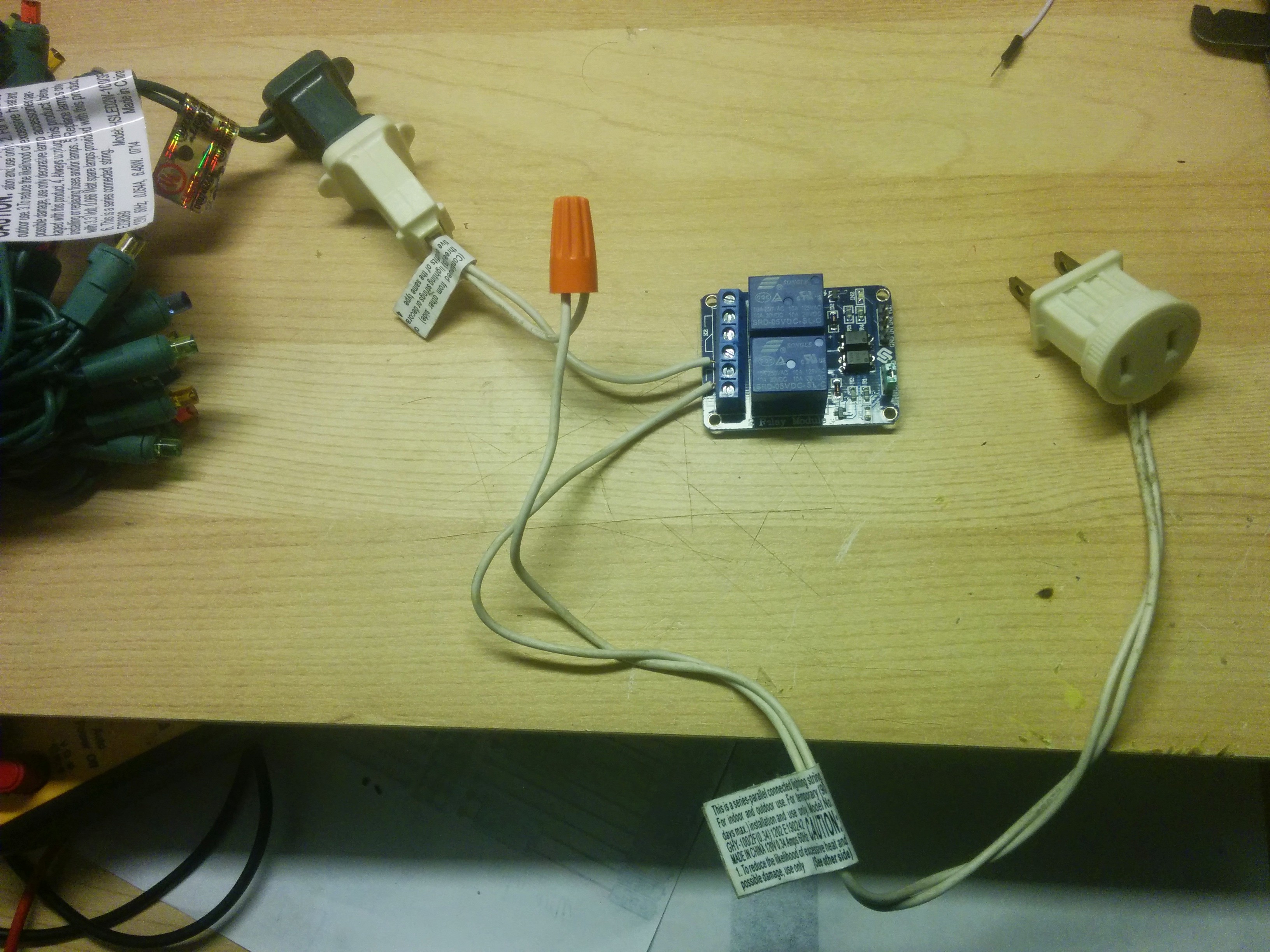
Hijacking the plugs off an old strand of lights, where one of the wires goes ‘straight through’ connected via a twist-on wire connector and the other wire goes through the relay, here is the setup for controlling 1 set of lights:
Relay set to control one string of lights.
Connecting up the Arduino to the relay involves connecting the 5V outputs previously used to drive LEDs now to drive the input lines on the relay board associated with the light strand we wanted to light. Due to inverted logic used by the relays, instead of driving a HIGH like we did before with LEDs, the relays now would need to be driven LOW in order to ‘activate’ (connect the lights).
(Yes, my engineer friends will tell me that if I had connected to the ‘normally closed’ ends of the relay then I probably could have left the drive logic alone, but as a Test Engineer at Freescale who has driven relays in this way for 10+ years, old habits die hard. Besides for safety reasons just felt that lights should be normally off when the system wasn’t powered).
With the kids we worked out roughly which notes we wanted to light which lights.
Then the kids made a couple of signs, one of which would house the Christmas lights and our holiday message.
It’s Time to Raise the Curtain…
Will share the code and hookup in a future post (stay tuned for the link).
The cool part is that hopefully with this setup we’ll be able to get the kids a bit more hands-on with the code in the spring! Wonder what song they’ll think up to do next…
Statler: That was a real wire act. Waldorf: On this show, everything’s a wire act. Statler: Why’s that? Waldorf: Because, you keep asking “Wire they doing it?”
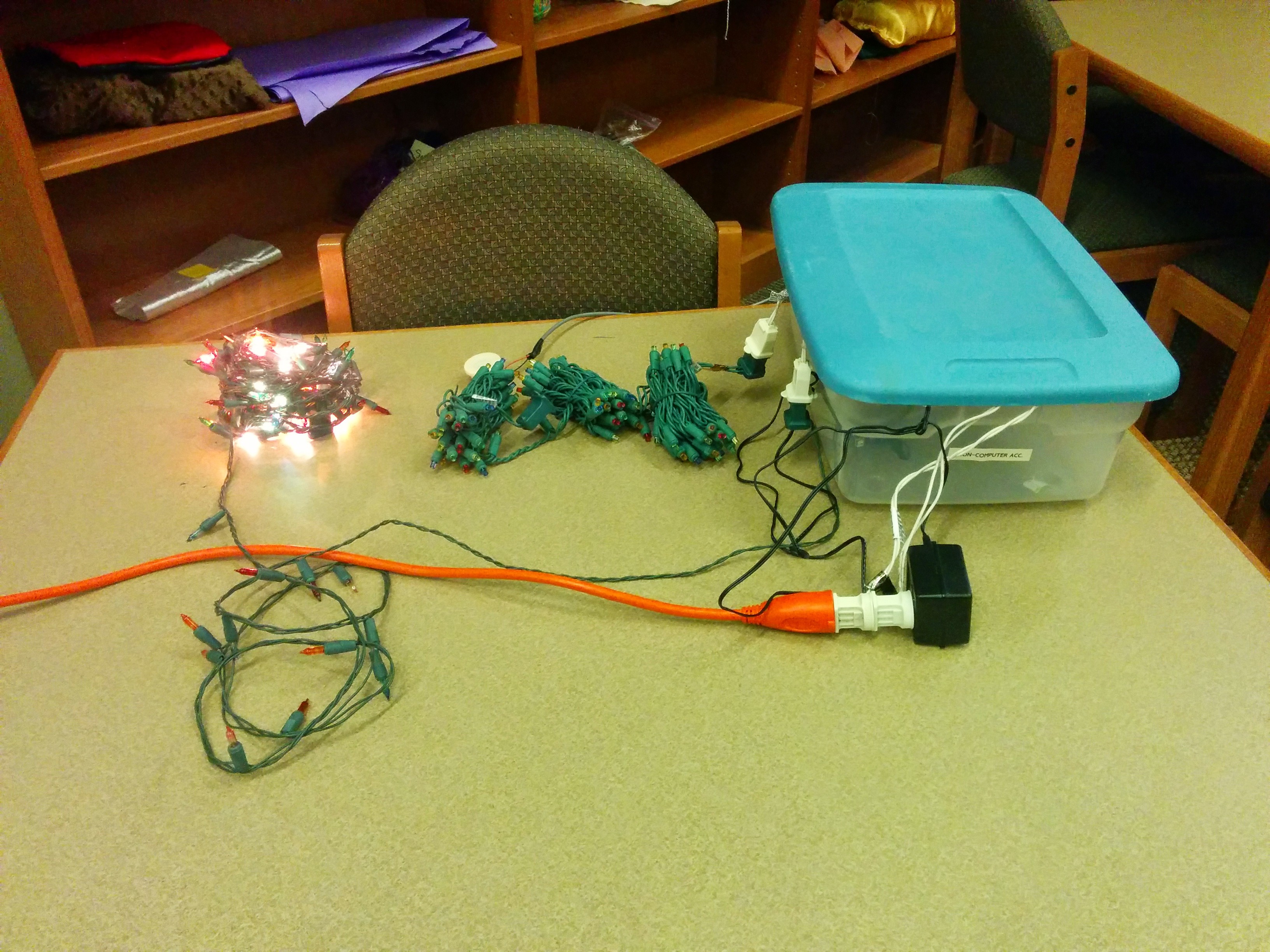
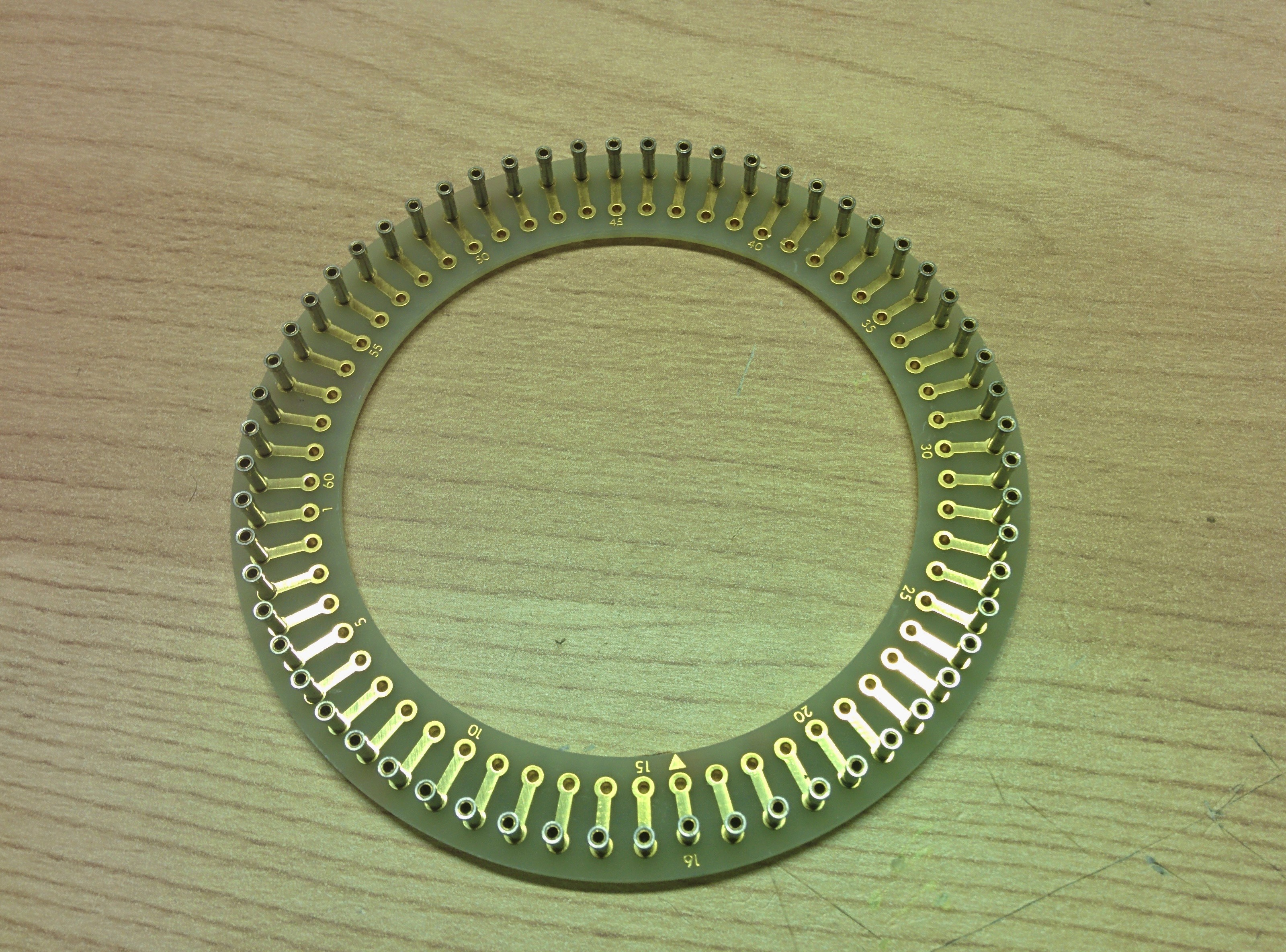
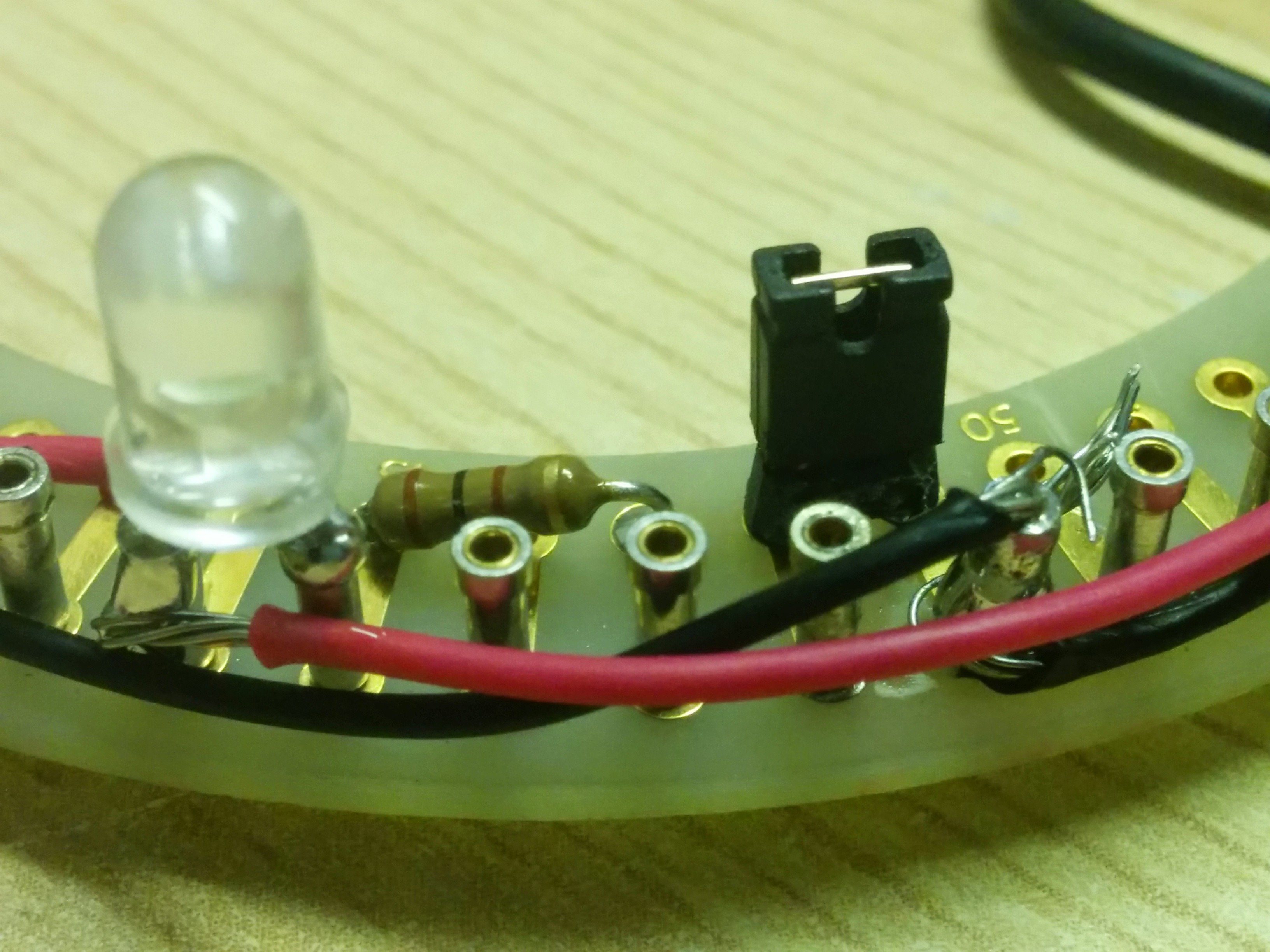
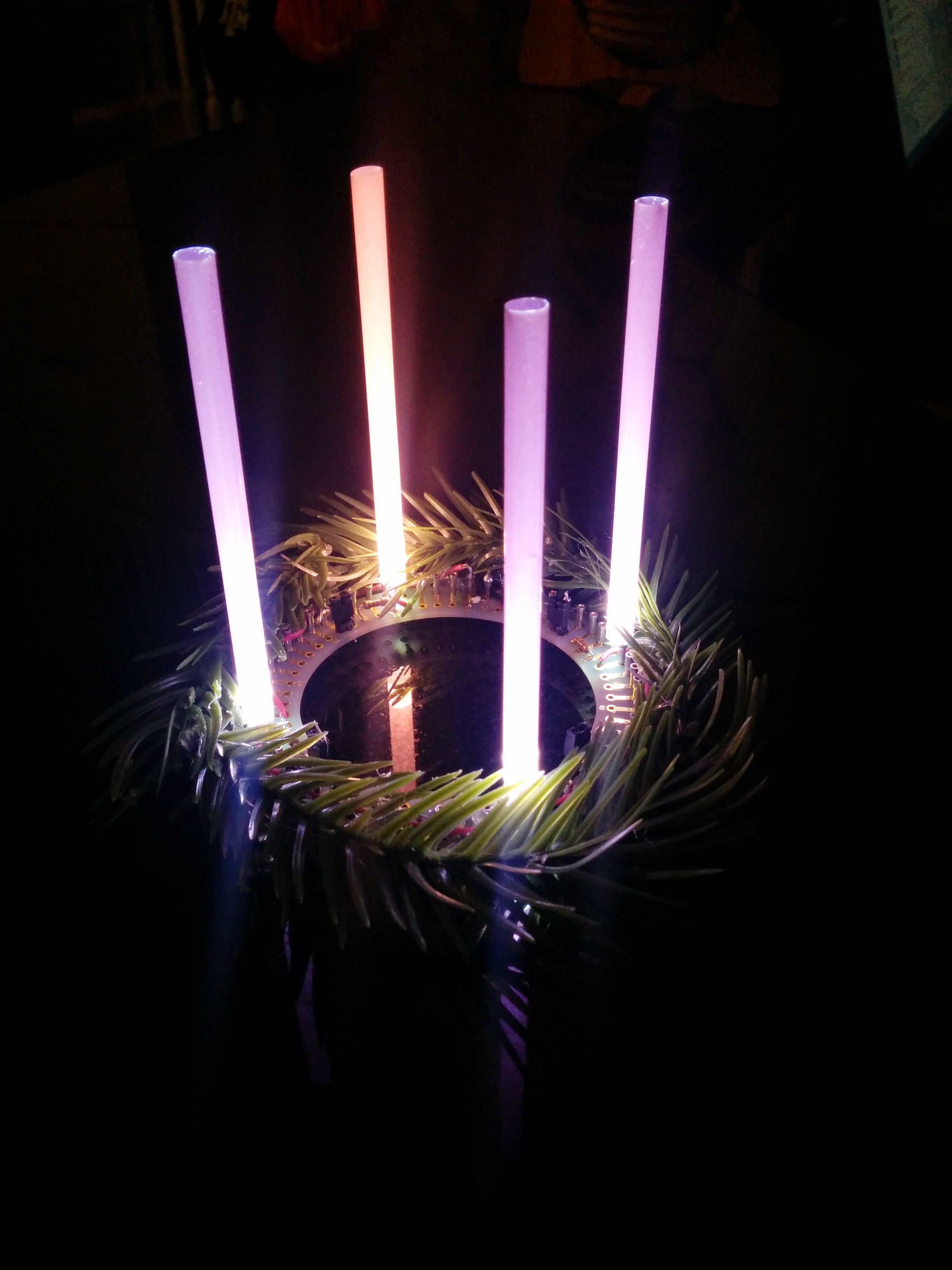
I had a circular PCB by chance (as I tend to grab everything I can get my hands on when being recycled!):
I needed something to be the ‘candles’. Initially was thinking to go with putting the LEDs on the top of real candles to simulate the flame. But most likely I’d be storing this with the Christmas stuff in the attic after Epiphany and due to the Texas heat we typically don’t store candles there.
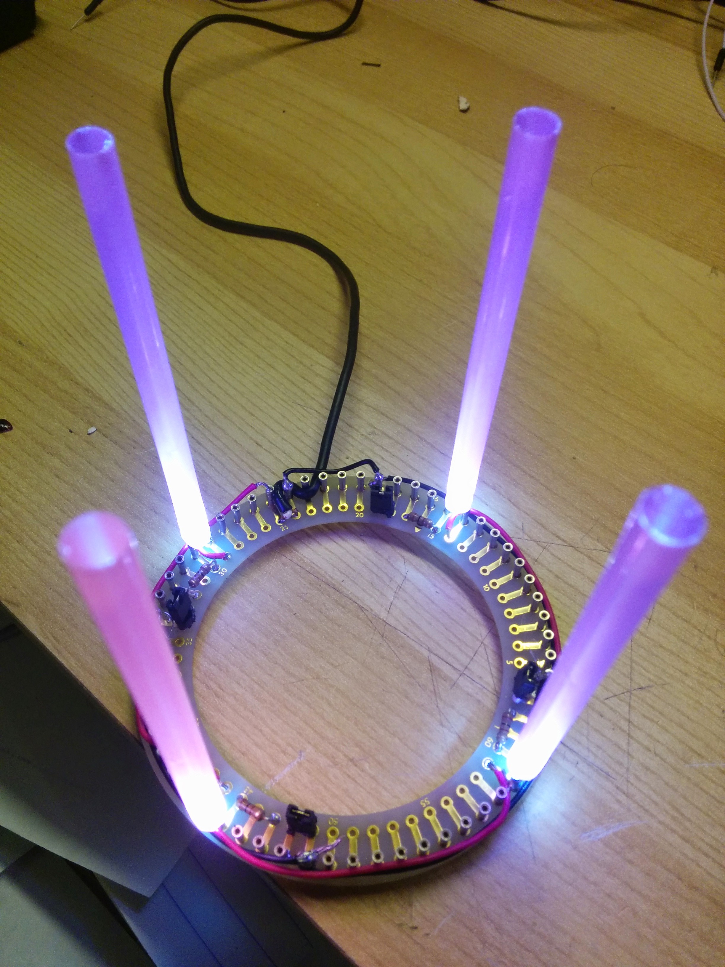
So after wandering around the store, thinking that I needed ‘magical colored plastic tubes’, I stumbled on these:
These perfectly fit on some white LEDs I had. I chose the most purpley and pink ones in the batch and cut them in half.
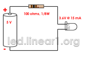
Next, in order to save myself replacing batteries and to keep the Advent Wreath lit as much as possible, I went and recycled a 5V Power Supply cable I had from an old bluetooth headset. (Electronics may die but power supplies live forever!).
Hooking up LEDs is generally very simple, you have to choose the proper resistor in series with them to limit the current through them. Wasn’t sure exactly on mine, but generally white LEDs have a forward voltage of 3.6V and can handle up to 20mA. I went with 100Ω per on online LED calculator (and because 100Ω is the smallest I have!).
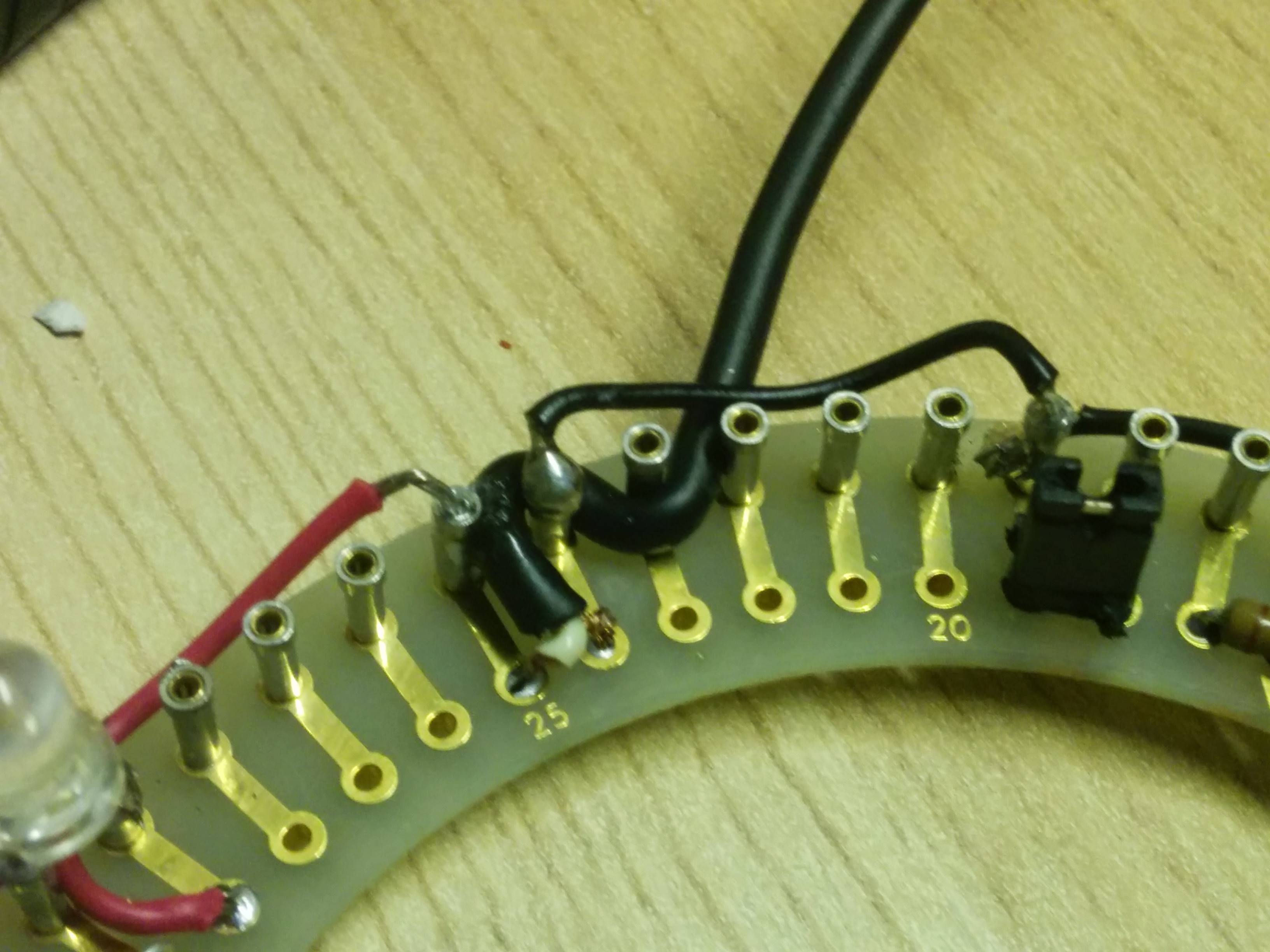
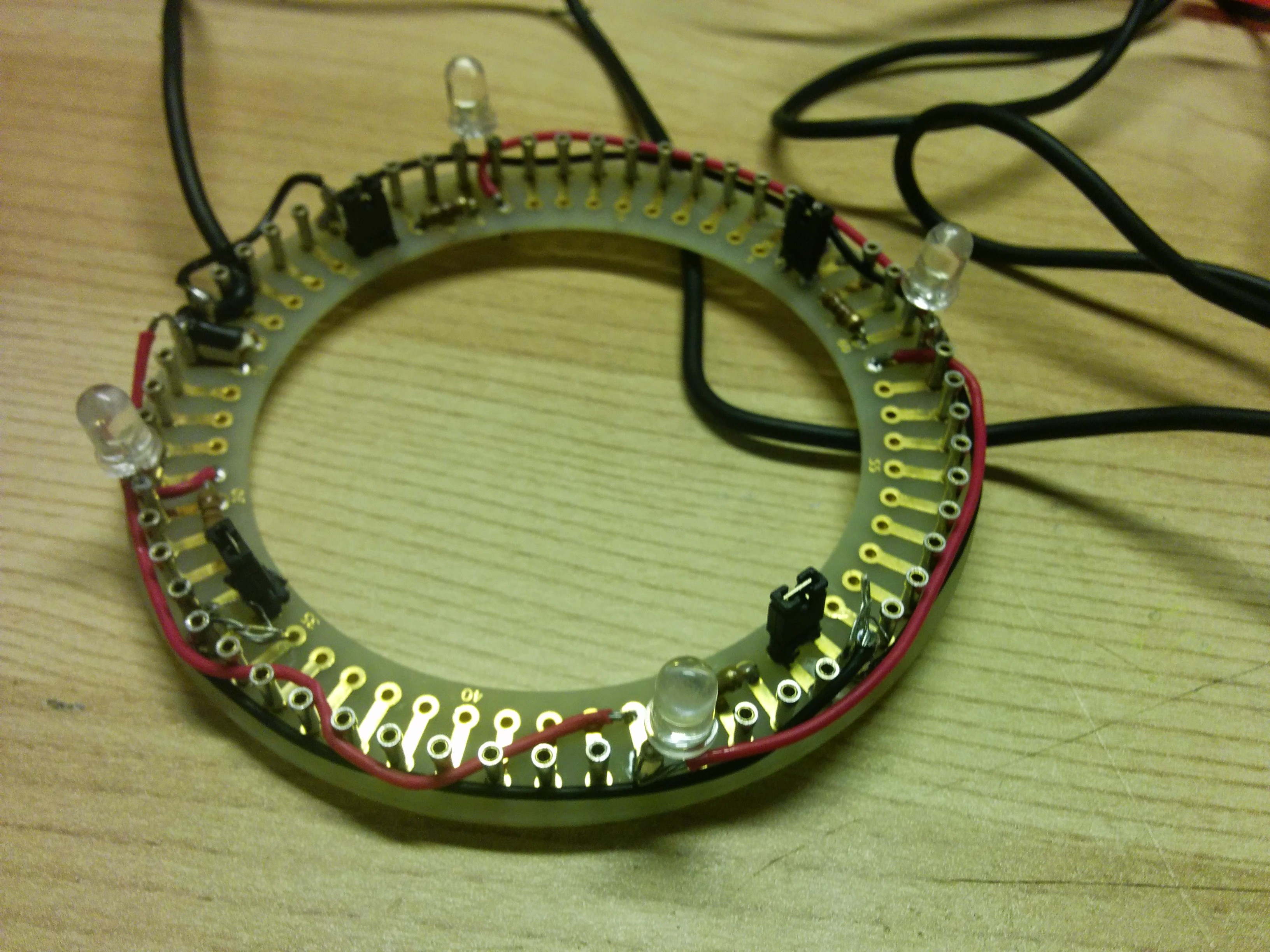
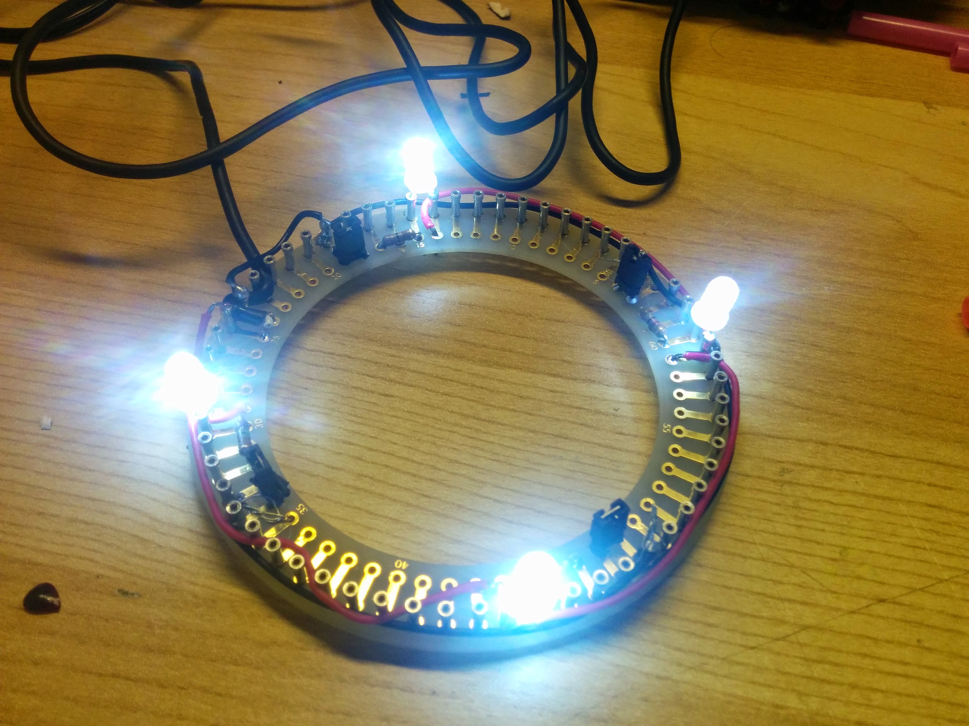
Hookeing everything up to the ring PCB, it looks like this:
5V power supply hookup
Added a way to ‘light’ and ‘blow out’ the candles using some jumpers:
One “candle”. Jumpers added to permit “lighting” the candle.
Almost done!
Lights on!
Straws attached
Found some old plastic wreath material:
Glue gun was already on the table! (Wife making a Christmas wreath):
Finis
Now I can keep this Advent Wreath lit much longer than usual! Happy Advent y’all!
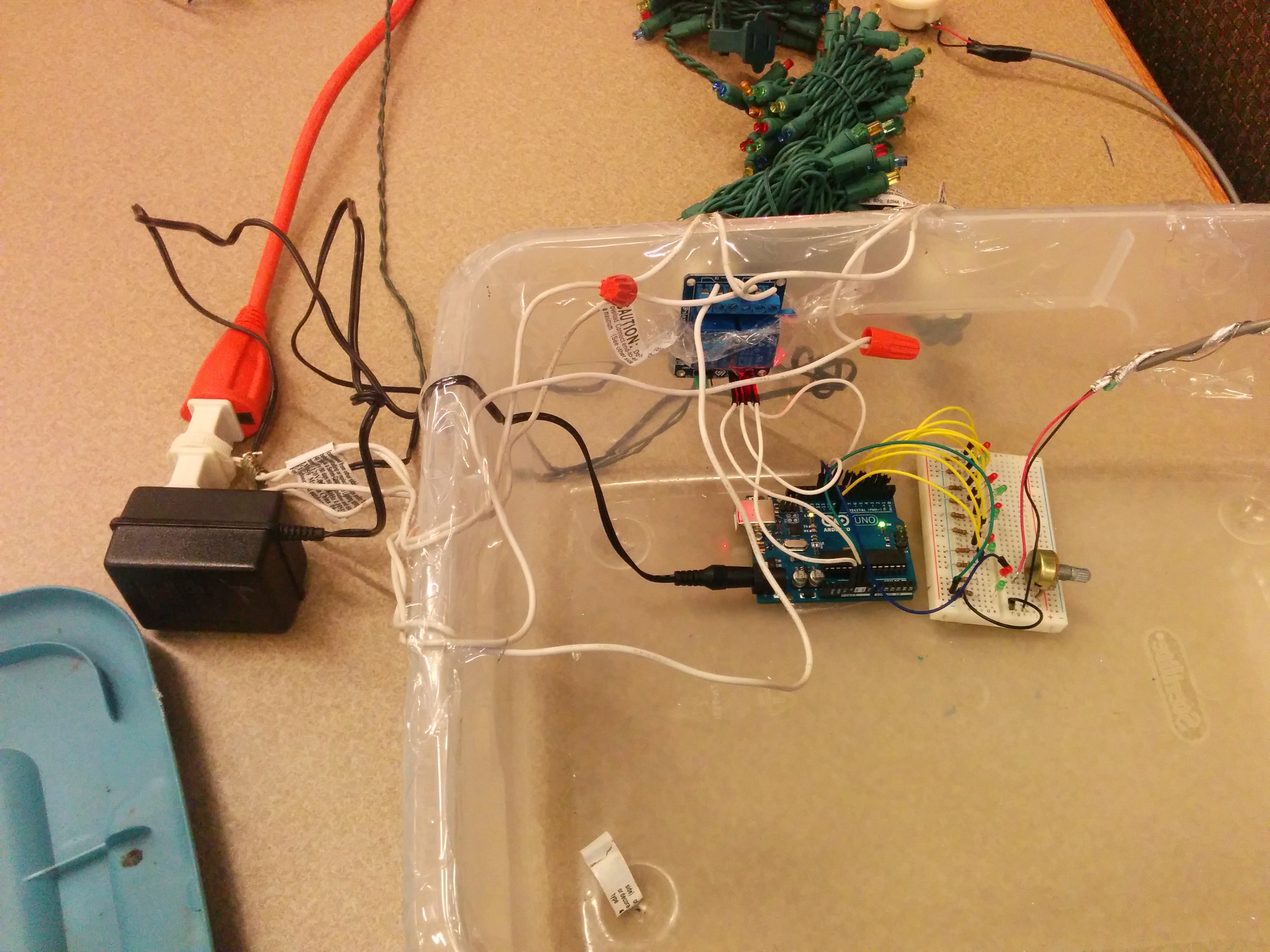
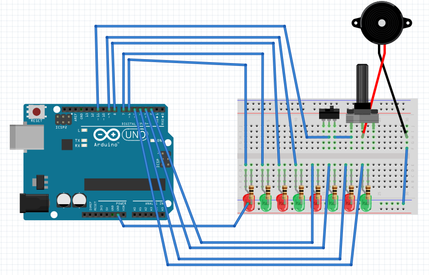
This is a little project I took on recently for my son’s afterschool Makerspace. The goal ultimately was to do something with Christmas lights, basically having an Arduino or something drive different strings of lights in time to some music. I would serve as tech consultant but let the kids drive the creative side, with some tech learning on the way.
So basically the project idea started from this : http://www.instructables.com/id/Arduino-Christmas-Light-Controller/. Got the relays, got the Arduino. I took this code and hooked it up to 8 LEDs via Arduino just to see if it worked. Got it working. The problem was that getting the music in sync with the lights requires you hitting play at the right moment. Also, doing a new song would require the kids to play a song over and over and measuring the time delays to update the program. Not exactly fun.
After some code update to make it easier for the kids to do their own songs, here we go.
Basically took a piezo speaker out of an old phone handset, hooked it up to pin 11 of the Arduino via a switch (for easy turn on/off) and a potentiometer (for volume control). I then added some code where you can assign one of the 8 LEDs to a particular note of the song, when it plays the note, it lights the LED.
Here is what I have so far:
Showed this to the kids on Thursday and they seemed to all enjoy it! They have started coding up Jingle Bell Rock note by note. Will keep you all posted on the progress!
Hookup and code is below. Enjoy!
And the code:
// From: http://www.instructables.com/id/How-to-easily-play-music-with-buzzer-on-arduino-Th/
// NB: ALL NOTES DEFINED WITH STANDARD ENGLISH NAMES, EXCEPT FOR "A"
// WHICH HERE IS CALLED "AA" BECAUSE A0,A1...ARE THE ANALOG PINS ON ARDUINO.
// (Ab IS CALLED Ab AND NOT AAb)
#define	C0 16.35
#define	Db0	17.32
#define	D0	18.35
#define	Eb0	19.45
#define	E0	20.60
#define	F0	21.83
#define	Gb0	23.12
#define	G0	24.50
#define	Ab0	25.96
#define	AA0	27.50
#define	Bb0	29.14
#define	B0	30.87
#define	C1	32.70
#define	Db1	34.65
#define	D1	36.71
#define	Eb1	38.89
#define	E1	41.20
#define	F1	43.65
#define	Gb1	46.25
#define	G1	49.00
#define	Ab1	51.91
#define	AA1	55.00
#define	Bb1	58.27
#define	B1	61.74
#define	C2	65.41
#define	Db2	69.30
#define	D2	73.42
#define	Eb2	77.78
#define	E2	82.41
#define	F2	87.31
#define	Gb2	92.50
#define	G2	98.00
#define	Ab2	103.83
#define	AA2	110.00
#define	Bb2	116.54
#define	B2	123.47
#define	C3	130.81
#define	Db3	138.59
#define	D3	146.83
#define	Eb3	155.56
#define	E3	164.81
#define	F3	174.61
#define	Gb3	185.00
#define	G3	196.00
#define	Ab3	207.65
#define	AA3	220.00
#define	Bb3	233.08
#define	B3	246.94
#define	C4	261.63
#define	Db4	277.18
#define	D4	293.66
#define	Eb4	311.13
#define	E4	329.63
#define	F4	349.23
#define	Gb4	369.99
#define	G4	392.00
#define	Ab4	415.30
#define	AA4	440.00
#define	Bb4	466.16
#define	B4	493.88
#define	C5	523.25
#define	Db5	554.37
#define	D5	587.33
#define	Eb5	622.25
#define	E5	659.26
#define	F5	698.46
#define	Gb5	739.99
#define	G5	783.99
#define	Ab5	830.61
#define	AA5	880.00
#define	Bb5	932.33
#define	B5	987.77
#define	C6	1046.50
#define	Db6	1108.73
#define	D6	1174.66
#define	Eb6	1244.51
#define	E6	1318.51
#define	F6	1396.91
#define	Gb6	1479.98
#define	G6	1567.98
#define	Ab6	1661.22
#define	AA6	1760.00
#define	Bb6	1864.66
#define	B6	1975.53
#define	C7	2093.00
#define	Db7	2217.46
#define	D7	2349.32
#define	Eb7	2489.02
#define	E7	2637.02
#define	F7	2793.83
#define	Gb7	2959.96
#define	G7	3135.96
#define	Ab7	3322.44
#define	AA7	3520.01
#define	Bb7	3729.31
#define	B7	3951.07
#define	C8	4186.01
#define	Db8	4434.92
#define	D8	4698.64
#define	Eb8	4978.03
#define R       0        // rest

// DURATION OF THE NOTES
#define H 2*Q //half 2/4
#define Q 60000/bpm //quarter 1/4  // Here assumes 4/4 time signature!
#define E Q/2   //eighth 1/8
#define S Q/4 // sixteenth 1/16
#define W 4*Q // whole 4/4
#define EE E*4/3 // slightly slow E or a quick Q

int speaker = 11;                      // WRITE HERE WHICH PIN THE SPEAKER IS CONNECTED TO
int leds[] = {6, 7, 8, 9, 2, 3, 4, 5}; // WRITE HERE WHICH PIN THE LEDS ARE CONNECTED TO:  1, 2, 3, 4, 5 ....
int num_leds = 8;                      // WRITE HERE TOTAL NUMBER OF LEDS CONNECTED

// The Imperial March
/*
int bpm = 120;      // WRITE HERE THE TEMPO OF THE SONG (BPM)
int song[100][2] = {  // WRITE HERE THE SONG IN FORMAT {{NOTE, DURATION}, {NOTE, DURATION}, ... {NOTE, DURATION}} MAX NOTES = 100
       {AA3,Q},{AA3,Q},{AA3,Q},{F3,E+S},{C4,S},{AA3,Q},{F3,E+S},{C4,S},{AA3,H},
       {E4,Q},{E4,Q},{E4,Q},{F4,E+S},{C4,S},{Ab3,Q},{F3,E+S},{C4,S},{AA3,H},
       {AA4,Q},{AA3,E+S},{AA3,S},{AA4,Q},{Ab4,E+S},{G4,S},
       {Gb4,S},{E4,S},{F4,E},{R,E},{Bb3,E},{Eb4,Q},{D4,E+S},{Db4,S},
       {C4,S},{B3,S},{C4,E},{R,E},{F3,E},{Ab3,Q},{F3,E+S},{AA3,S},
       {C4,Q},{AA3,E+S},{C4,S},{E4,H},{AA4,Q},{AA3,E+S},{AA3,S},{AA4,Q},{Ab4,E+S},{G4,S},
       {Gb4,S},{E4,S},{F4,E},{R,E},{Bb3,E},{Eb4,Q},{D4,E+S},{Db4,S},
       {C4,S},{B3,S},{C4,E},{R,E},{F3,E},{Ab3,Q},{F3,E+S},{C4,S},
       {AA3,Q},{F3,E+S},{C4,S},{AA3,H}
};
int num_notes = 70; // WRITE HERE HOW MANY NOTES IN THE SONG!
int led_notes[] = {Ab3,AA3,F3,C4,E4,F4,Gb4,G4};  //WRITE HERE WHAT NOTES TO LINK TO WHICH LEDS, MUST BE SAME NUMBER AS NUMBER OF LEDS ABOVE!
*/

int bpm = 100;
int song[100][2] = {
 {C6,E},{AA5,E},{B5,E},{AA5,E},{G5,Q},{AA5,Q},{Bb5,Q},{B5,Q},{R,Q},{C6,E},{C6,E},{C6,Q},{B5,E},{B5,E},{B5,Q}
};
int num_notes = 15;
int led_notes[] = {C6,AA6,B6,G5};

/*
// Super Mario Bros (1985) Overworld / Main Theme
int bpm = 240; // want slightly faster
int song[100][2] = {
       {E6,E},{E6,Q},{E6,Q},{C6,E},{E6,Q},{G6,H},{G5,H},
       {C6,Q+E},{G5,Q+E},{E5,Q+E},{AA5,Q},{B5,Q},{Bb5,E},{AA5,Q},{G5,EE},{E6,EE},{G6,EE},{AA6,Q},{F6,E},{G6,Q},{E6,Q},{C6,E},{D6,E},{B5,Q+E},
       {C6,Q+E},{G5,Q+E},{E5,Q+E},{AA5,Q},{B5,Q},{Bb5,E},{AA5,Q},{G5,EE},{E6,EE},{G6,EE},{AA6,Q},{F6,E},{G6,Q},{E6,Q},{C6,E},{D6,E},{B5,Q+E},
       {G6,E},{Gb6,E},{F6,E},{Eb6,Q},{E6,Q},{Ab5,E},{AA5,E},{C6,Q},{AA5,E},{C6,E},{D6,Q+E},{G6,E},{Gb6,E},{F6,E},{Eb6,Q},{E6,Q},{AA6,Q},{AA6,E},{AA6,H}, //60
       {G6,E},{Gb6,E},{F6,E},{Eb6,Q},{E6,Q},{Ab5,E},{AA5,E},{C6,Q},{AA5,E},{C6,E},{D6,Q+E},{Eb6,Q+S},{D6,Q+S},{C6,H}
};
int num_notes = 74;
int led_notes[] = {AA5,B5,E5,G5,C6,E6,F6,G6};
*/

void setup() {
  pinMode(speaker, OUTPUT);
  for (int i=0; i < (num_leds-1); i++) {
    pinMode(leds[i], OUTPUT);
  }
}

// turn on LED that matches note
void leds_on(int note) {
  for (int i=0; i < (num_leds-1); i++) {
    if (led_notes[i] == note) {
      digitalWrite(leds[i],HIGH);
    }
  }
}

// turn on LED that matches note, turn off all others
void leds_on_v2(int note) {
  for (int i=0; i < (num_leds-1); i++) {
    if (led_notes[i] == note) {
      digitalWrite(leds[i],HIGH);
    } else {
      digitalWrite(leds[i],LOW);
    }
  }
}

void leds_off() { // turn off all LEDs
  for (int i=0; i < (num_leds-1); i++) {
    digitalWrite(leds[i],LOW);
  }
}

void play_note(int note, long duration) {
  int blink_lights = 1;  // false

  if (blink_lights == 1) {  // Turn on LED corresponding to note, if any
     leds_on_v2(note);
  }

  if (note != R) {                 // only play if not a rest
    tone(speaker, note, duration); // http://arduino.cc/en/Reference/Tone
  }
  delay(duration);

//  if (blink_lights == 1) {  // Turn off all LEDs
//     leds_off();
//  }

  delay(1); // note separator

}

void play_song(int which_song) {
  //int len = sizeof(melody)/sizeof(int);
  for (int i=0; i < num_notes; i++) {
    play_note(song[i][0], song[i][1]);
  }
}

// the loop routine runs over and over again forever:
void loop() {
    play_song(0);
    delay(1000);
}