So I was getting ready to write my next blog entry for the Magic Cooler, when….
Well, Esquilo!(squirrel in Portuguese) anyway!
The founders of Esquilo came to visit at work this week. They have a Kickstarter going on for their Esquilo Air board, a wifi-enabled development board targeted specifically to enable simple IoT (internet of things) setups to the Maker Community!
Freescale purchased some of the boards BEFORE the Kickstarter has ended and handed out to those intrepid folks willing to make it into something.
Pre-Kickstarter is cool.
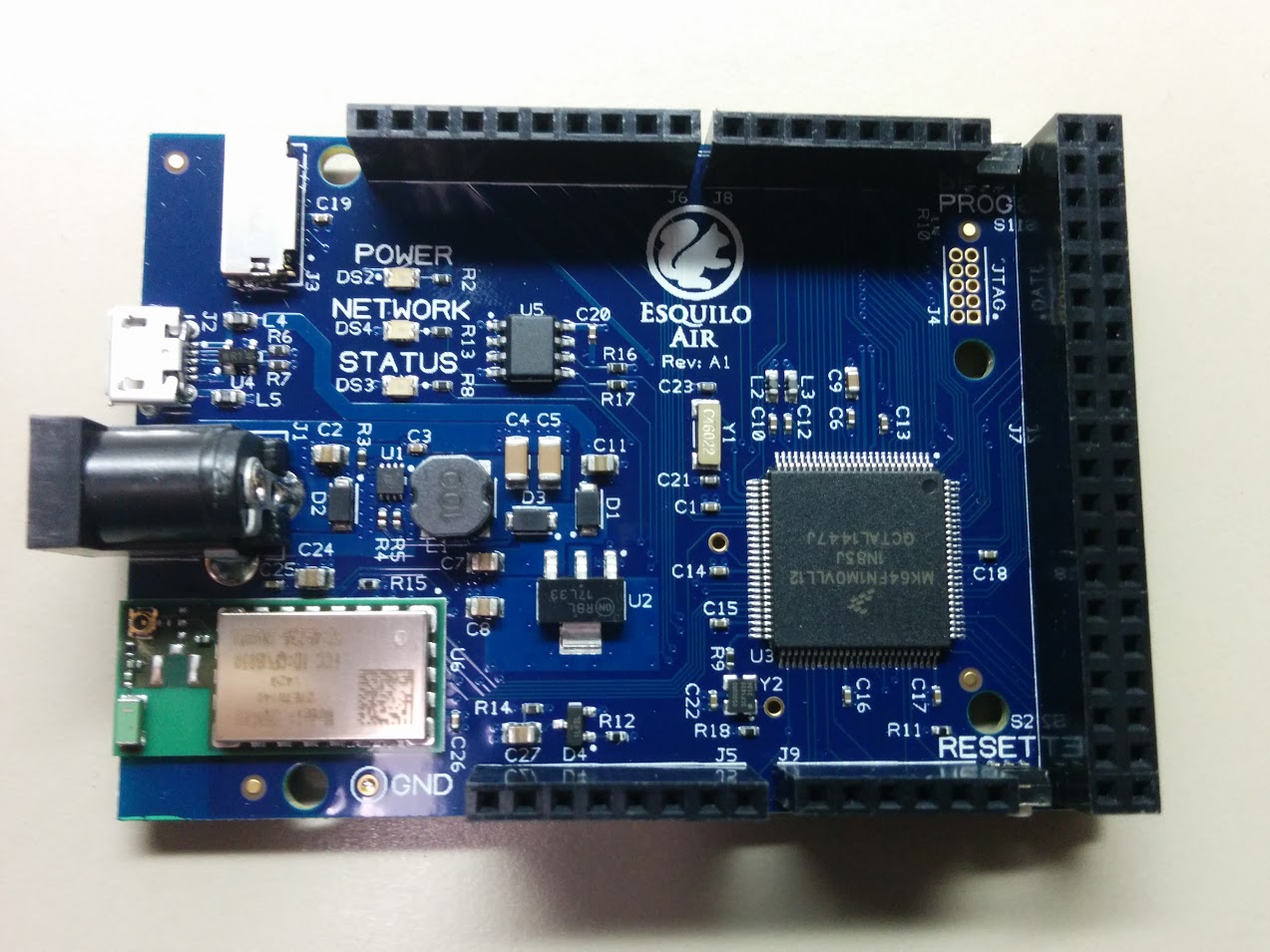
What is the Esquilo board you ask? Here it is:
Internet of Squirrel?
The “Air” board has Arduino-compatible pin headers, a micro SD card slot, and an awesome K64F FSL Kinetis micro with 1MB of flash! (not biased or anything).
Most importantly the board has built-in Wifi whose drivers have already been loaded on there. Everything is built-in on this board! Including the IDE! Plus it uses the Squirrel language, which is dynamic, so no compiling and loading!!
That’s right. From what I understand while not having yet played with it– is that the board having built-in Wifi capability lets you connect to it via your computer browser, like you would any router or access point. Then you write your code or load it in there. Then run it. No internet required. No USB required (unless you want for power). You can load code via the on-board micro-SD slot.
Very excited to see how this will work out and have many ideas for how I want to use it.
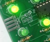
At Austin Maker Faire 2008, I bought a simple board from LadyAda, aka Adafruit Industries, that exhibited Conway’s Game of Life. The so-called ‘Game of Life’ is a zero-player ‘game’ where a 2-dimensional grid with an initial state is defined and then time is allowed to proceed according to certain ‘life rules’. Each LED of a 4×4 grid represents a ‘cell’ and over time either dies, lives or reproduces according to these rules.
Adafruit “Game of Life” modular board
The board is very well made and designed so that you can interconnect many of these boards together so that you can construct a much larger LED array to make the ‘game’ much more interesting as there are more ‘cells’.
But… I didn’t really have any interest in getting more boards after the first, and the Game of Life really gets boring after a while (to me). So for a while I’ve since been thinking of an alternative use for this little board.
Noticing a binary clock in a coworker’s office the other day I had the idea to reprogram the Game of Life board to be my own binary clock.
Binary Clock
A binary clock is simply a clock that represents the digits of the time in a binary encoded fashion. It’s basically a clock to show off a bit how nerdy you are, that you can read a clock that others possibly can’t.
Binary Coded Decimal Clock
Most Binary Clocks represent each of the 6 decimal digits of the time (HH:MM:SS) with a separate binary value through the on/off state of the LEDs in a column. Technically, this is Binary Coded Decimal format, as each digit in decimal is represented by a separate 4-digit binary number.
In any case, given that the Game of Life board has 16 LEDs, 4 rows of 4 columns each, I could use it to represent HH:MM (no seconds) of the time. I would be wasting 3 of the LEDs of the first digit as it is either 1 or 0 (12hr time notation, 24hr notation it would be 0, 1 or 2 I suppose).
The first job to change the function of the board is to change the program running on the microcontroller. To do that required learning and understanding how to reprogram an AVR-based microcontroller.
Do what?
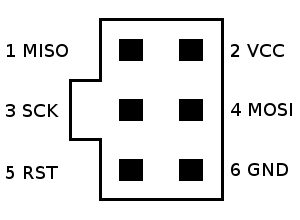
Thankfully, they added a 6-pin ICSP interface on the board.
ICSP stands for In-Circuit Serial Programming and is used to program the memory of a microcontroller while still sitting in the system. (Some micros can only be programmed by being removed from the board and put into a separate, dedicated programmer).
So I added a pin header to the ICSP port on the board and proceeded to figure out how to reprogram using this interface.
AVR programming setup
The microcontroller used on this board is an Atmel Atmega 48V, a little cousin to the Atmega 328P used on the Arduino Uno R3 board. This micro uses the Atmel AVR architecture so it will require an AVR programmer in order to modify the flash program running on the micro.
Looking on Amazon, found an AVR programmer called the USBASP v2.0. Since the programmer uses the 10-pin version of the ICSP interface, so I also had to get a 10- to 6-pin adapter board. Total spent on these: $15 (and can use them for any future AVR programming!).
Ready to reprogram!
NOTE: Be sure when plugging in the 6-pin interface to the board to get the proper orientation as it can be easy to reverse it since the connecter doesn’t enforce it. Check that the GND pin of is on the lower-right as you look at the ICSP port.
NOTE also that I temporarily removed the battery connection from the board as the USB connection will power the board. Will put it back once I’m happy with the final product so it can run standalone.
Next step: writing the new code to load onto the micro and loading it!
Binary Clock Code
Looking online I was able to find the original source for the Game of Life firmware that came preprogrammed on the board on GitHub. This also includes the schematic for the board which will be helpful if I ever want to modify the board in the future. It’s also important when programming a micro to obtain its data sheet so we know how it works. The data sheet for the Atmega48V micro is available from Atmel here.
I started out figuring out how to properly drive the LEDs. The 16 LEDs are directly connected to each of the 8 pins of Ports B and D of the microcontroller. This is the simplest way to drive LEDs from a micro, albeit not the most pin-efficient.
Setting a bit to a 1 drives the corresponding output pin high and lights the LED. Setting it to 0 turns off that LED.
For example, these values generate a simple letter D:
PORTB=0b01100000; //60
PORTD=0b11111001; //F9
The plan is to treat each of the columns of LEDs as a value, then encode PORTB and PORTD to properly represent those values.
For this I wrote a small function called display_by_column() that basically takes 4 integers and drives that value in binary on each of the 4 columns of LEDs.
The next step would be to figure out the current time, break that up into 4 digits and send that to display_by_column().
Counting Time
A clock is simply a counter that counts seconds and displays them in a base-60/base-12 kind of way. This “counter” permits any initial value so that you can “set” the clock.
First job was to count seconds. A basic way to do this is to have an infinite loop that increments a 32-bit unsigned integer variable called time with a delay of 1 second per loop (using _delay_ms(1000) ).Since this integer has a maximum value much greater than the number of seconds in a day, a maximum check was added to the code so that at the approppriate time it will roll over back to 1:00.
A second job is to calculate the amount of hours and minutes that have expired based on the current time in seconds.
Third, take the number of minutes and apply modulo 60 so that the value of minutes of 0-59. Do the same for hours using modulo 12 (so that the value is 0-11). Since we measure time in 12-hr format using 1-12 we increment the hours by 1.
Finally, we obtain the 10s and 1s digits for both the hours and minutes so we have 4 values to pass to display_by_column().
This works really well to count the hours and minutes that have elapsed since ‘time began’, starting at 01:00 and going to 12:59, which for this project begins when you plug in the device.
Setting the Time
A proper clock lets you adjust the time to match the current time so that it’s a useful time indicator.
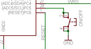
The board already has a switch, so let’s see if we can repurpose it. Looking at the board schematic, this momentary switch is connected to pin PC5, which has dual purpose of PCINT13, or Pin Change Interrupt 13.
Pin PC5 was already set up in the code as an input via the corresponding data direction register. It was also set up to have an internal pull-up resistor. What that means is that the PC5 input will be high (1) normally, unless the switch is being pushed, in which case PC5 will read as a low (0).
To keep things simple, I added the code that reads PC5 at the start of the infinite loop. If it sees it, it increments the time by 60 seconds. In order that we change the time faster then 1 minute per second, the loop delay is momentarily reduced to 100mS while the switch is being pushed.
Although not using the interrupt, I decided for now this is sufficient for setting the time, since if we increment the time too fast the user may go past their intended time target. If I later add a second switch, I may decide to properly use the external hardware interrupt.
Last thing is to program the new firmware to the board!
For this I needed 2 things:
The USBASP driver for use with Windows for the USBASP programmer.
WinAVR for compiling the code and flashing the device.
WinAVR, pronounced ‘whenever’, is a basic command-line utility that can be used to reprogram firmware onto an AVR processor and can be obtained from http://winavr.sourceforge.net/.
Details on that procedure are here, but basically it uses a special GCC (Gnu GCC compiler) called avr-gcc for the code compilation.
It is critical that the Makefile be updated so that the proper AVR programmer is indicated:
AVRDUDE_PROGRAMMER = usbasp
Finally, just execute the compile and flash to board in one go:
make all
Fin
This was a fun little project for me to help learn a few things about an AVR microcontroller and to repurpose a board that was just gathering dust. Yes, I could have just bought a binary clock from Amazon, but where’s the fun and the learning from that?
Ok, this really is a nanowonder! Admittedly, this chip came out by Freescale last year but I just received it in a business card like format:
Did you miss it? That’s the MCU (microcontroller unit) there in the little window set into the card next to the lifesize image of a pushpin.
“I love it when we put things on the head of a pin!”
The KL03 (as of last 10 months), claims to be the smallest ARM-powered MCU at an uber-tiny size of 2mm x 1.61mm! Most importantly the height of the chip is only 0.56mm, making it very easy to come up with all kinds of applications!
The form factor is WLCSP (Wafer Level Chip Scale Package) which instead of using pins uses tiny solder balls that you heat up as you drop the chip onto a board:
With such a tiny device you might wonder what can you really do with it? First off with only 20 pins I took a look at the pinout diagram to see what exactly I could access:
Besides VDD and VSS (power and ground), it appears you can access 11 pins of Port A (PTA0,1,2,3,4,5,6,7,8,9,12) and 7 of Port B (PTB0,1,2,3,4,5,13). These of course are multiplexed to permit access to I2C, GPIO and UART interfaces as well as a 12-bit ADC. What is most impressive is that there is an ARM Cortex M0+ core inside that can go up to 48MHz and the device is self-booting (has its own boot ROM)!
The application for this little guy is the so-called “Internet of Things,” or IoT. Since it is very small it consumes very little power at 50uA/MHz. You set the clock as high as your application may require but not too high to minimize power consumption.
I have no idea yet what applications are using the KL03, but I would imagine things like having them implanted in small, wearable devices or inside smart light bulbs, light switches, etc. I’ll let you know here as soon as I see one “in the wild.”
With its 256kB of Flash, 64kB of RAM, and 72MHz processor, it fits between an Arduino Uno and Arduino Due in capabilities, although closer to the Arduino Due, which has 512kB of RAM. It is roughly the cost of the Arduino Uno, with almost all the capabilities of the Arduino Due!
And all that in a roughly 13mm x 36mm size board!
I see great things coming…
Yummy, yummy!
“Even better, longer lasting”
(Above: 5 Teensies in a box of gum. Wonder what I’ll do with them??)
Late last month I received my second Arduino, which took a bit longer than usual to arrive, and when it did, it came directly from China in a small package. There was not the usual colorful little box and package of stickers, which made me suspicious.
Sure enough, looking more closely revealed that I have one of the fake arduino boards.
Here they are side by side:
Left: Fake, Right: Authentic
Since Arduino is an open source board design it stands to reason that there would be some similar boards designed, or derivatives that are Arduino-compatibles, but they shouldn’t try to attempt to pass themselves off as the original and definitely not infringe on the trademark.
Since I have a fake, I thought it would be fun to note what I could spot as differences before attempting to return it (don’t want to encourage this sort of behavior). NOTE that the Amazon ad from which I purchased it said it was the OFFICIAL one but several commenters noted they received fakes as well. So be careful when ordering!
Definitely noticed the color differences off the bat. But on closer inspection also could see also other differences:
Note the green 501k resistor on the left (fake) under the USB port. Arduino has their own 501k resistor custom made to stand out (right).
Generally, the soldering job on the fake was worse quality. Note the crystal oscillator (oblong silver thing left of center) is not soldered in straight on the fake. Also:
Note the silk-screening is better on the real one (right) vs the fake (left). The hole in the “A” is missing on the fake. Generally, through holes are not as well done on the fake as well.
The boot of Italy is not as well formed on the fake (left), although at first glance it seemed ok. Notice the distance between the tip of the boot and the island of Sicily.
One might say “what does it matter?” Well, besides the fact that it encourages illegal trademark infringment, you might not get as high quality a board, that may break over time.
Notice here the poor soldering job done on the fake (left). The 4th pin from the left on the bottom isn’t even soldered completely! This is sad also because there are purple marks on the board indicating someone had to have inspected it at some point! Who knows what kinds of problems you would have to debug with the fake board!
A couple of big indicators, 1, no silkscreening on the pin headers:
and the biggest thing of all, no board number on the corner of the board!
I’ve given a 1-star review of the vendor on Amazon and will be reporting them for trademark infringement per the recommendation on the Arduino official page.
Hopefully I’ll get my money back, stay tuned.
In the future need to check the list of official vendors here, I guess imitation is a form of flattery, but in my mind it’s just an attempt to grab a piece of the DIY Arduino market.
At least with this one it was easy to tell, I’m sure I have other undiscovered fakes in-house.
Look carefully!
UPDATE
Been in contact with the Arduino Trademark people after reporting the seller to them. Sent them some detailed pictures, shown here: http://goo.gl/gTY1pj
Also, after some back and forth with the seller they have refunded my money ($15 which should have been a hint as to the fact it was counterfeit), without asking for the board back. Won’t use it. It will serve as a reminder to be careful ordering these and other boards in the future.
Working on names the other night for a new blog I’ve been wanting to do, it occurred to me that somehow relating it to my other internet endeavor, skywonders.com, might make some sense. That enterprise, still having its own fits and starts, was started mainly as a way to show my sense of utter amazement and wonder at the universe we humans find ourselves in. The utterly large Continue reading


![lunar_module_as12-51-7507b[1]](http://www.nanowonders.com/wp-content/uploads/2014/11/lunar_module_as12-51-7507b1-226x300.jpg)