Joy to the World!

First of all, sorry it’s been a while since my last post.  More articles to come in 2016!

Since then, I did manage to take the Magic Cooler and use it to run the Christmas lights on my house with some minor upgrades to the software and minor updates in the cooler.  If you’re not already familiar with the Magic Cooler, see it explained in Part1 and Part2 from previous posts.

https://www.youtube.com/watch?v=LBgu77rin3E

My daughter painted the sign showing what FM frequency to tune to to listen in (it was later changed to 88.3MHz since many tuners can’t handle ‘even’ frequencies).  My son helped code up some of the songs.

The house was hooked up with 9 separate sets of lights. The nativity scene was the only one kept constant, the other 8 would be controlled by the music playing.

Lighting plan done in GIMP

Each note in the song is assigned to one or more of the relays that controls one of the light sections.  This way synchronizing the music to the lights is much easier than the usual manual method of associating beats to music, although this method does require coding up each song manually.  A side benefit is that you can involve those more familiar with reading music than C code to add new songs to the ‘mix’.   More on the music-to-code methodology in another article (maybe I’ll make my first Instructable!).

The music is output to an FM transmitter instead of a speaker, so as to not bother the neighbors and to permit those driving by to listen to the music on their car radios.

Where the Magic Happens

Minor updates I did to the cooler in the pic above include:

  • Add an IDE ribbon cable to connect from the control signals at the bottom of the box up to the prototyping platform on top.   These are connected to the middle breadboard, as to permit  connecting any microcontroller board in the future if desired.
  • Switch added to go between Play and Test modes.
  • Momentary pushbutton (yellow) added to help test out the relays and various light connections.  Repeatedly pushing thus button goes from all off, turns on relays one a time, then turns them all on (no relays actually activate when all are told to turn on due to current limitations of the system).
  • Extension USB cable added for USB hooked to Teensy control board to permit easy reprogramming of the board.  Hope to upgrade in the future to permit wireless reprogramming or control of the board (as a side benefit I did figure out how to reprogram using Arduino IDE on my Chromebook using Crouton OS– very neat and portable!).

Updates I’d like to do:

  • Make PCB for the relatively constant parts of the control system– LED indicator lights, audio output, pushbutton and DIP switches.
  • Upgrade to solid state relays to permit more relays to be on at once.
  • Add LED to indicate which song is playing at the moment.
  • Add USB hub for easier 5V power distribution on prototyping platform.
  • Code updates to permit even completely automatic note-relay assignment.
  • Add WAV playing capability of each note so that it sounds better.
  • Add capability to play 4 part harmony type music (will sound better).
  • Make software library to make code easier to manage online, allow users to submit songs remotely.

Let me know if you have any other suggestions by giving a comment!

Merry Christmas!!

Making Magic In A Cooler – Part 2

Welcome to Part 2 of the Magic Cooler project.  If you missed Part 1, you can read it here. 

Thus far we have focused only on building the AC circuit that will serve to directly control the 10 switchable lights via 10 relays.

Now, we want to hook up the Teensy 3.1 board to control those relays in time to music, and have the Teensy drive the music itself out to a speaker of some sort.  The Teensy 3.1 board uses the Freescale Kinetis K20 microcontoller.

For controlling the relays, I used 10 of the Teensy board GPIOs.   These were configured in software to serve as digital outputs.   Since the relays used negative logic, i.e. a logic 0 activates the relay, the LEDs on the circuit were set up to also use negative logic so that the same GPIO on the Teensy board activates both an LED and a relay.   The LEDs on the circuit protoboard will help in debugging any issues with the relays and give a reminder that the code is running properly.  For this project, pins 13-22 were used for LED/relay control.  (See the board pinout chart here).  Pin 13 also controls an LED directly on the Teensy board– so we have yet another ‘heartbeat’ to remind that the code is running.

The speaker or headphones are connected to one of the PWM-capable outputs of the Teensy.  PWM stands for Pulse-Width Modulation and basically is an output signal that looks like a square wave.  The Arduino IDE tone() function used in the software permits generating a square wave of variable frequency.  When this square wave is applied to a speaker, you get a sound of that frequency!  For this project, PWM-capable pin 23 was chosen for sound output.

The diagram below shows how the Teensy protoboard circuit was wired up.

teensy_circuit

Teensy Circuit Protoboard

Appropriate valued resistors must be chosen for the above circuit depending on the LEDs and speaker used to limit the current through each.   For my circuit, I used 1.3k ohm for the LEDs and 100 ohm for each of the 2 ‘channels’ of the headphone jack.  2 different resistors were connected to each of 2 sides of the jack in order to get stereo sound from the computer speakers.

The top of the circuit diagram above shows the 12 wires that will serve to control the relays:

  • 10x digital logic control of each relay (white)
  • vdd / power (red) (in actuality 2 of these were needed to power the 2 relay boards)
  • ground (black) (in actuality 2 of these were needed to ground the 2 relay boards)

Here is the actual board used:

IMG_20150513_173020

Shown with computer speaker wire connected

The board is powered by a standard micro USB cable connected to a USB AC adapter plugged into the ‘always on’ AC outlet.

Next, we hook up the board to a simple set of computer speakers to make sure it works:

https://www.youtube.com/watch?v=y0DAuEe6r7Q

(In this video you can still see the black speakers we were initially going to use attached to the side of the cooler, but we decided against them at the last minute.  Computer speakers worked out just fine.)

The next step was to hook it up to the relay boards!  The 14 wires had to be ported through a hole in the clear protective guard then through one of the clamp connector holes in the metal junction box.

IMG_20150513_172502

Control wires

Once the control wires are in the metal box, they had to be carefully attached to the control, supply and ground pins of the 2 relay boards.

IMG_20150513_173027

We have control!

Now that everything is wired up, it’s time to run some music and lights!

Here in the Freescale MakeIt Lab we ran a full light test:

https://www.youtube.com/watch?v=20Dsus8Gr4o

(Not shown:  One of the ‘songs’ added was a music scale which was a perfect was to test out the lights!)

Stay Tuned for Part3, where we review the software and how easy it is for kids to program it!


Making Magic in a Cooler – Part 1

Andres and I were finally able to complete the Magic Cooler project and present it at the Freescale booth at Austin Mini Maker Faire 2015!  Now to document!

This project started out as something to help educate kids in learning to control Christmas lights with music using a microcontroller in an easy-to-use environment last year in the Makerspace for my son’s middle school.  At that time, we used an Arduino Uno, but I was able to pretty easily convert to using the much more practical and powerful Teensy 3.1 thanks to the Teensyduino software add-on.

The most challenging part of that Makerspace music project was the AC circuit side of the hookup.   To not modify the Christmas lights being controlled, I had to cut off the plugs on some sacrificial Christmas lights to serve as the controlled outlets.

I had since wanted to do a project upgrade, using regular AC duplex outlets to control many more lights!  And fit it all into a portable, rugged “box” of some sort.

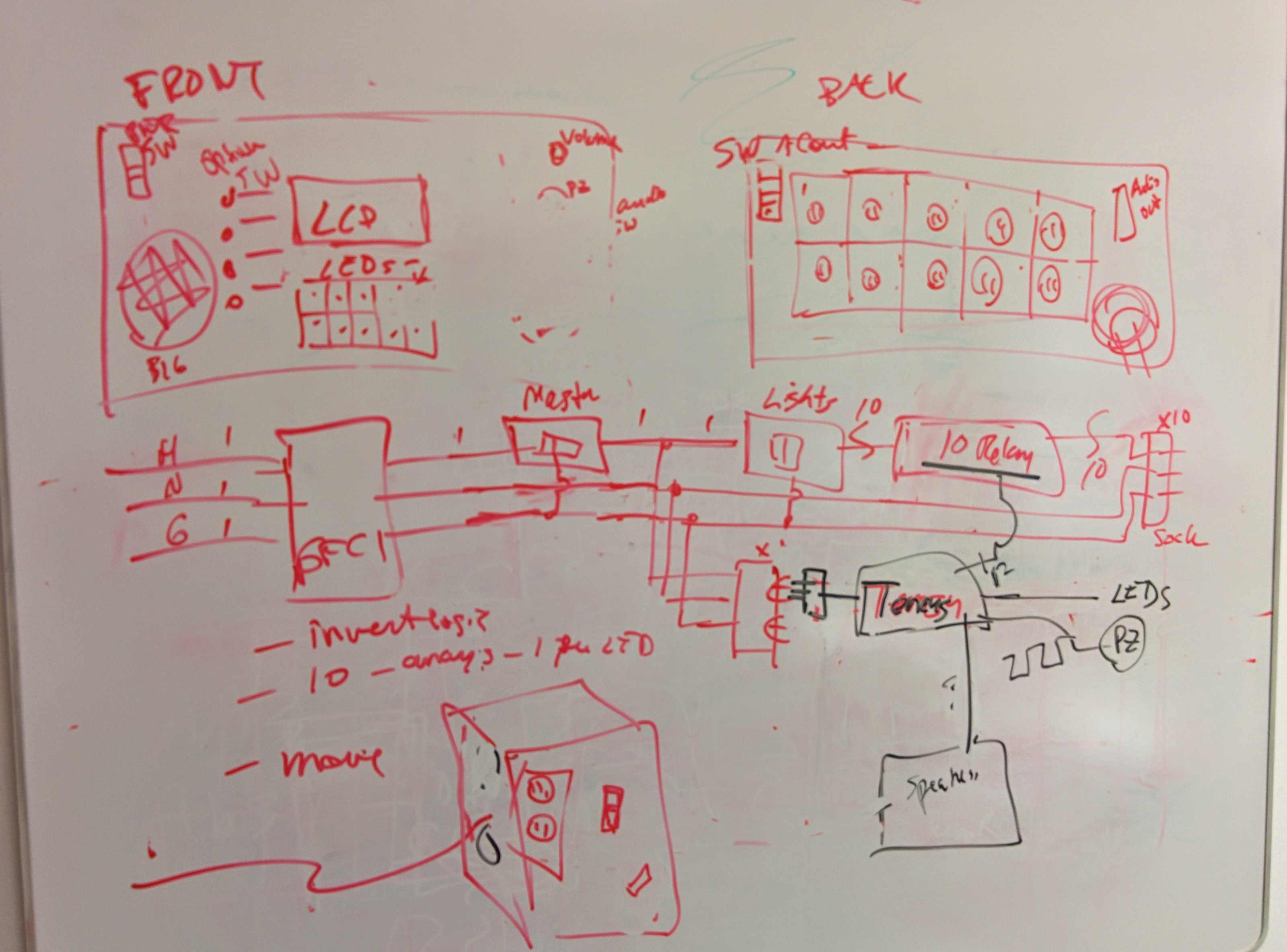
As with any project, I started off with some thoughts:

IMG_20150227_153045

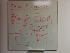
Initial concept drawing

IMG_20150409_180125

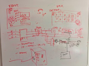
A bit of circuit diagram in there.

Initially, I had wanted to use a cheap, black toolbox to house the AC circuits.  But after some measurements of the interior, it seemed a bit cramped for what I wanted to add, and the walls seemed too thin to support installing the ‘blue boxes’ needed to properly contain the AC outlets.

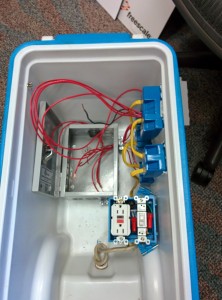
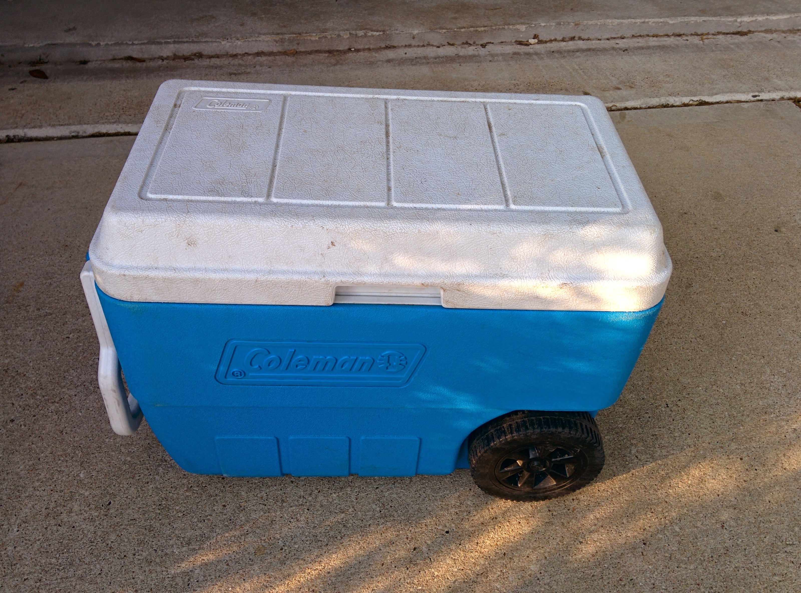
Fortuitously, I was cleaning out the garage around this time, taking stuff to Goodwill.   As I was putting this blue Coleman cooler with broken lid hinges into the trunk of the car, it hit me that this would be the perfect container for a portable music and light show:

IMG_20150401_185649

All kinds of possibilities!

It has 1″ thick walls, lots of room inside, a handle and wheels!  The lid not being hinged on is actually a plus as it allows removing the lid completely to permit work inside.

Part 1 of this article will focus on the physical and AC electrical side of the build.

Electricity and Safety

I wanted first and foremost for the AC part to be as safe as possible.  Just like in the walls in your house, what that means is containment of all connections via blue boxes and a master junction box.  It also means having a circuit breaker or a ground-fault circuit interrupter.  I chose the latter.

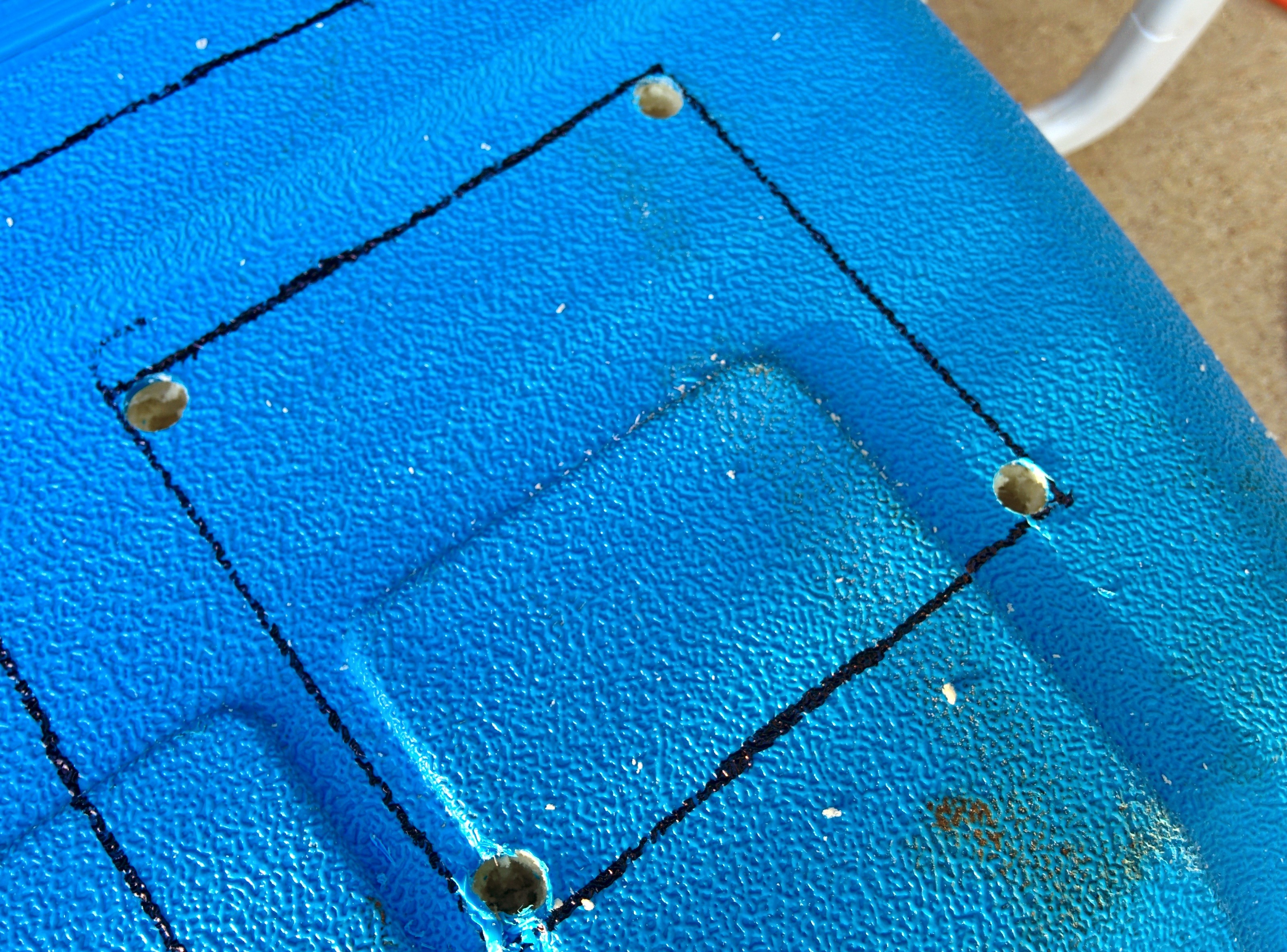
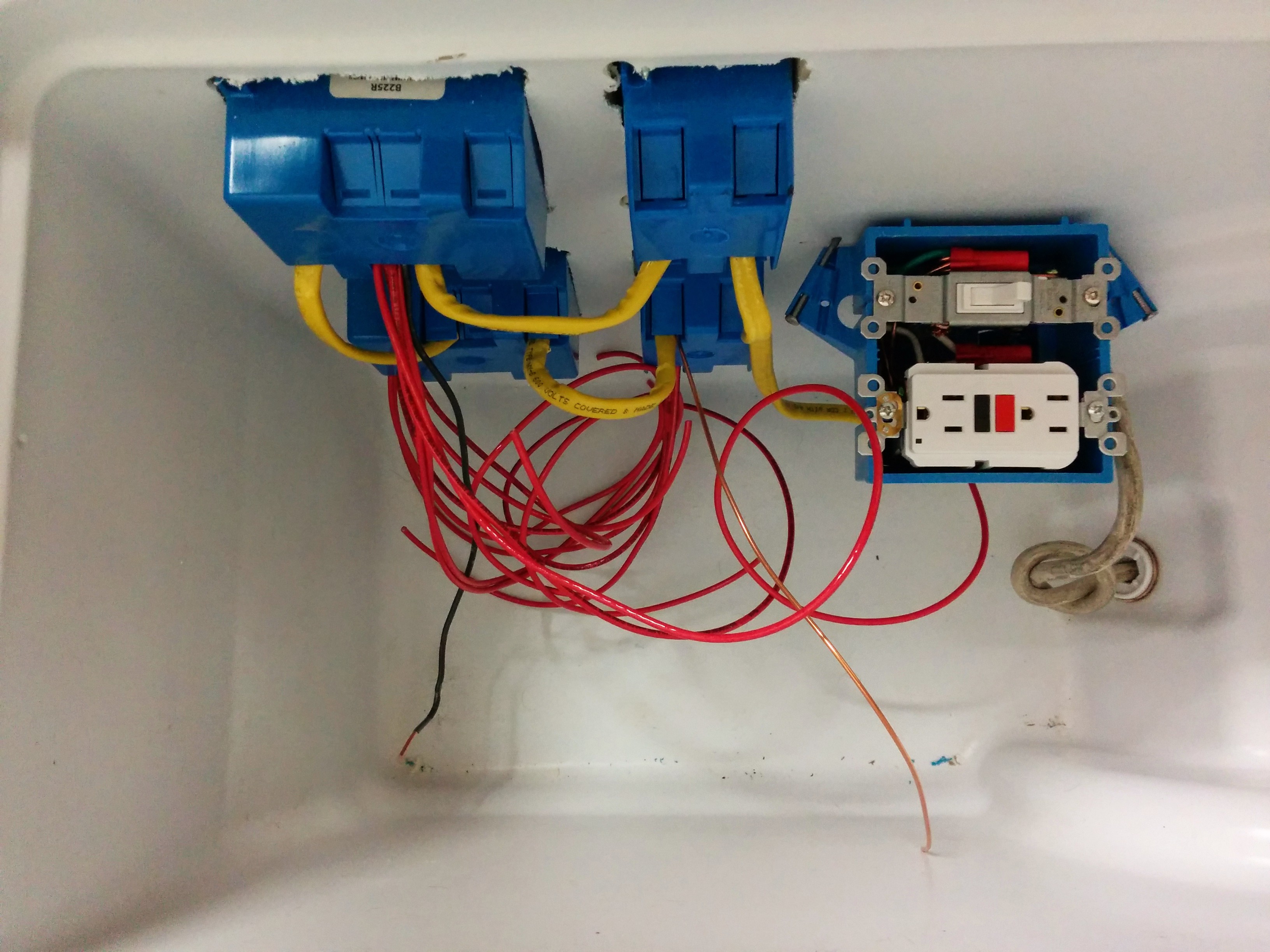
Step 1: Install the AC blue boxes and outlets in the sidewalls of the cooler.

I wanted to have 10 outlets total as I have 10 relays available for control, which means having 5 duplex outlets.   I also wanted a simple light switch to help to turn off all exterior outlets if necessary, for safety reasons and to permit debugging code and music without having to worry about driving the external lights.  The outlets were planned to be on the ‘back side’ of the cooler.

Out came the cutting tools…

IMG_20150401_185716

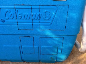
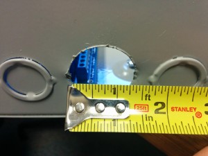
Outline for blue boxes on Cooler back side.

IMG_20150401_185818

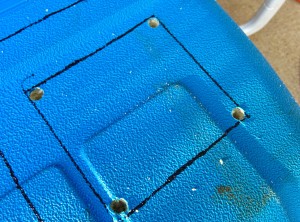
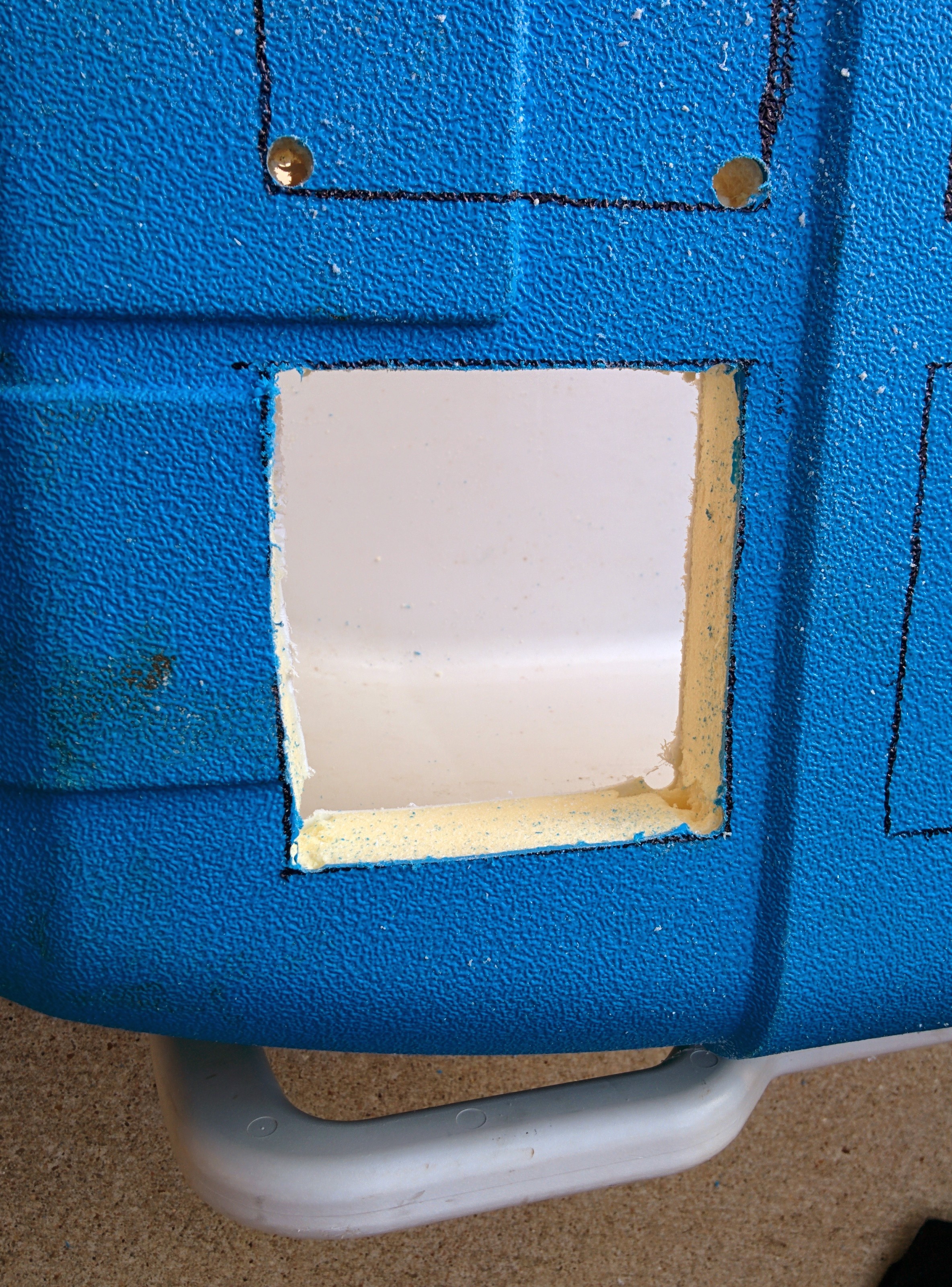
Holes drilled at the corners. Used a bit large enough to permit inserting jigsaw blade later.

IMG_20150401_190831

Used a jigsaw inserted into the corner holes to cut out the rectangles.

IMG_20150401_191802

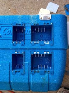
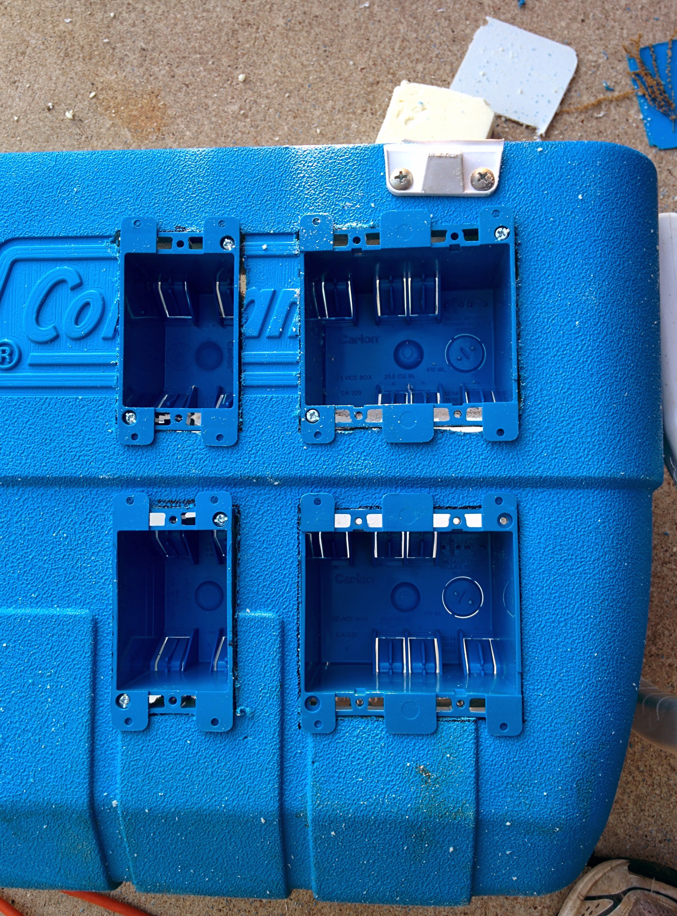
Screwed in the boxes.

Normally, in a house wall you’d want to attach these blue boxes to a stud behind the drywall.  However, in this case the plastic exterior and interior of the cooler were tense enough to support the boxes.

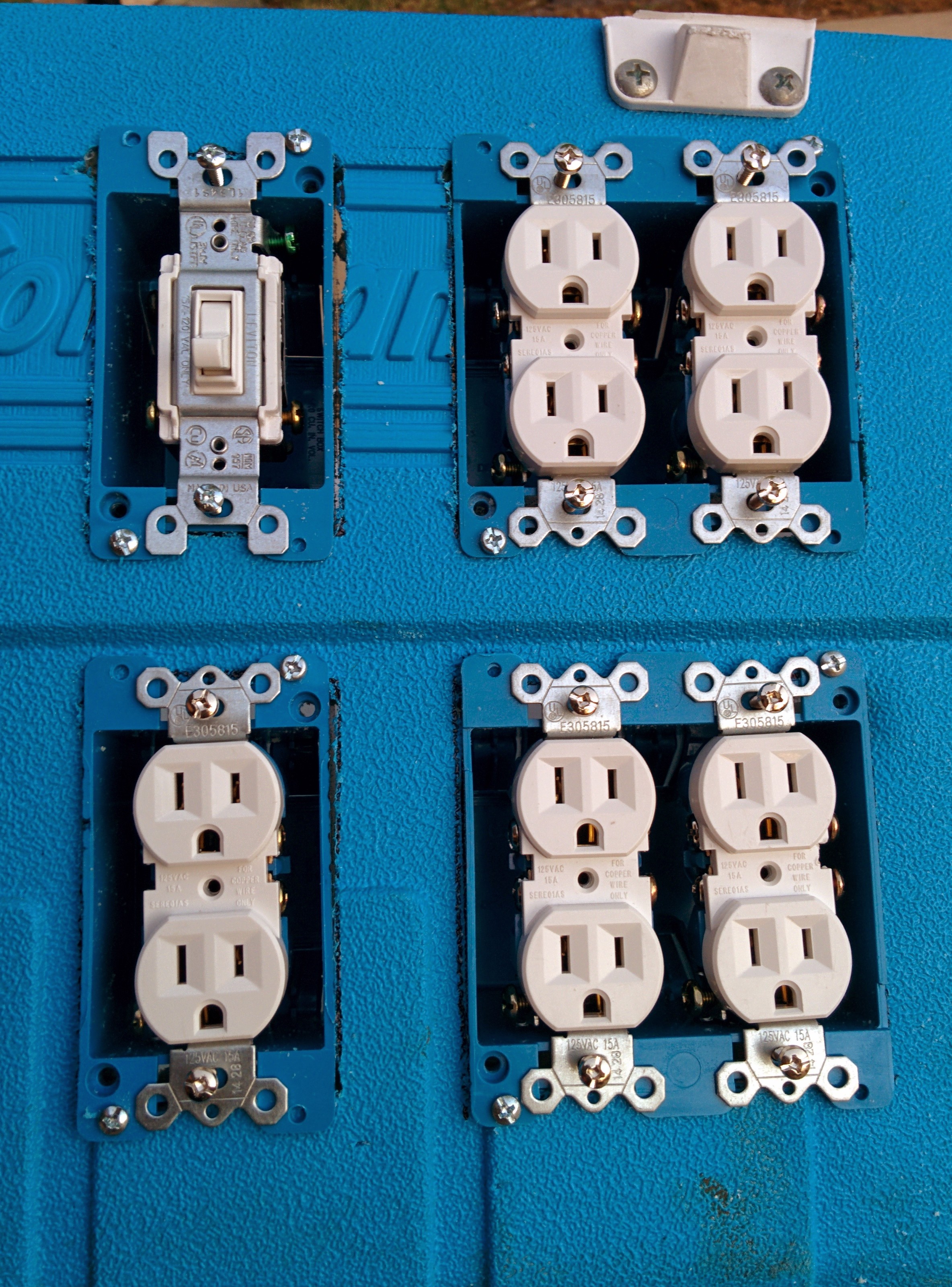
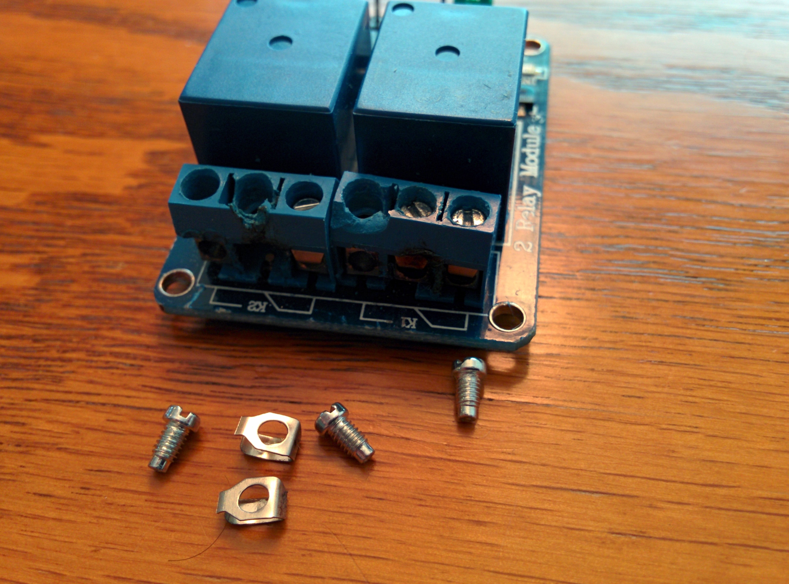
The next step was to loosely install the AC outlets to check the fit.  I planned to remove them again later when doing the final wiring so here just installed them mainly as a placeholder.  Prior to the install, since I wanted to individually control the outlets later, I went ahead and removed the tab connecting the hot sides together.  I used pliers to wiggle the tab back and forth to break it off.

IMG_20150401_194919

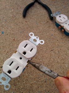
Removed hot side tab shorting the two outlets together.

IMG_20150401_194940

Tab removed.

IMG_20150401_195539

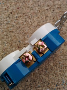
10 outlets and 1 switch added.

Wiring

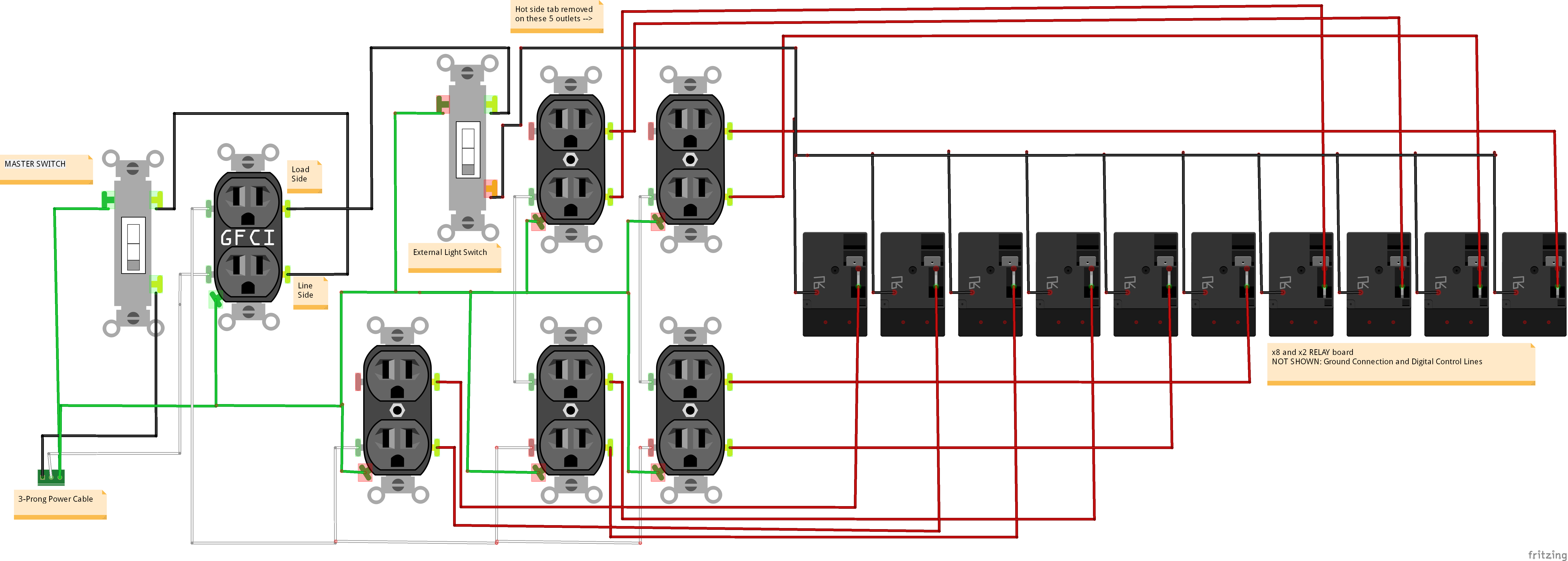
Step 2, wire up the AC circuit.  Here’s a diagram showing the AC side of the circuit:

AC_circuit_bb

AC side of Magic Cooler Circuit

Basically, power comes in to the Cooler via a 3-prong wire (hot-neutral-ground) and goes through a master switch and a GFCI outlet which will be located inside a separate blue box inside the cooler and serves to protect the remaining outlets downstream.  Let’s follow each line separately:

  • Ground (GREEN):  Directly connects to every ground screw you can find.   Not shown above is the ground connection to the metal junction box housing the 10 relays.
  • Neutral (White):   Connects to LINE side of GFCI outlet– comes out of LOAD side of the GFCI receptacle and connects to the Neutral connector of every downstream outlet.
  • Black (Hot):  Connects to LINE side of GFCI outlet– comes out of LOAD side of the GFCI receptable and connects to the secondary Light Switch.  Hot leaves this light switch and connects via a bus terminal to the Normally Open side of each of the 10 relays.
  • Red (Switched Hot):  Connect from the common terminal of each of the 10 relays to the Hot screw for each of the 10 switched outlets.

I used #12 Romex to do the wiring, although I probably should have used something smaller gauge for the short runs here as #12 is difficult to work with (hard to bend), but at least now I know the circuit is very robust.

IMG_20150423_182819

Main blue box wiring done.

I ran the 3-wire Romex box to box just as is done in a house wall.  However, after the first set of duplex outlets the hot (black) wire was removed from the Romex bundle and brought down to where the future junction box would be.  Red wires were connected to the hot side of each of the 10 outlets and also run down to where the junction box would eventually be.

I decided that the GFCI receptacle and master switch should be located inside the cooler.  The GFCI provides some protection from accidental touching, wires coming loose creating shorts, and would help if I ever planned to take the Cooler outside.   It would also serve as a standard outlet to power the microcontroller board and other accessories.

Since the Cooler already had a nice, convenient drain hole, I decided to use that to run the main power cord.   I cut the power cable from a 10-outlet power strip so was confident it had sufficient current-carrying capacity. A knot was added to prevent from accidental tugs on the power cord from damaging the internal wiring.

Next step, the junction box.

Junction Box Prep

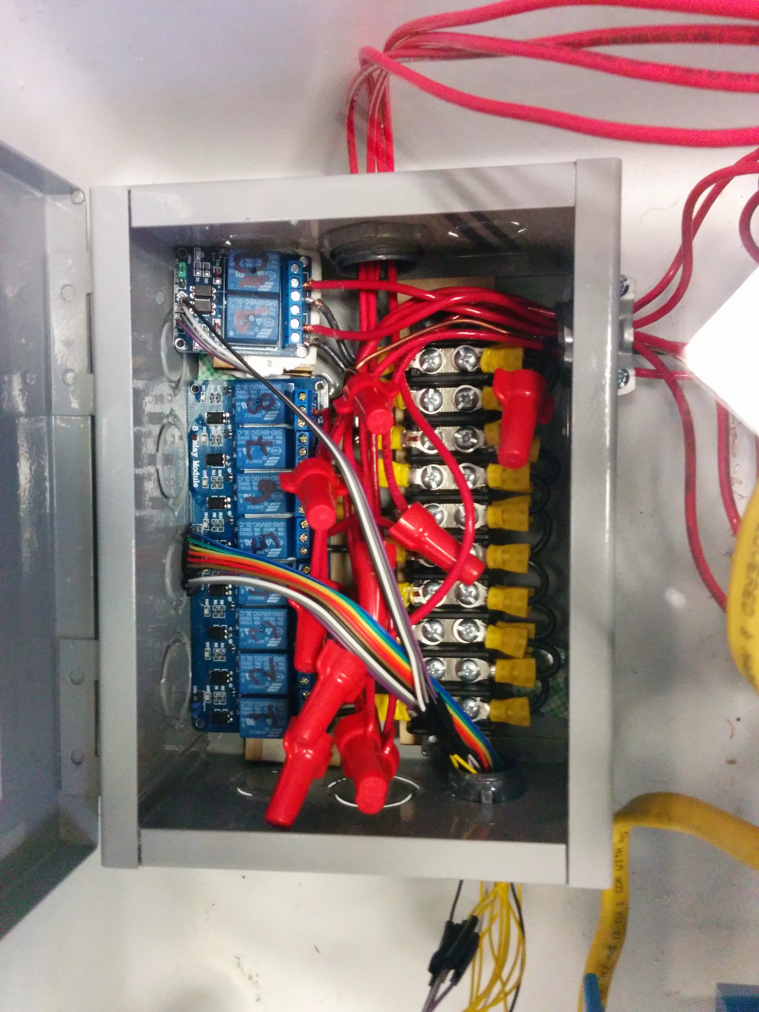
The junction box was used to house the bus terminal to expand the single hot (black) wire to the 10 relays and the connection of those relays back to the switched outlets (red wire).  In case of any electrical fire or loose wire, the box would serve as containment and/or ground.

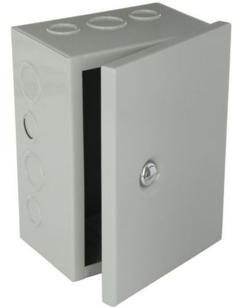
Some electrical stuff is just cheaper to get on Ebay than at your local hardware store, so I found a really nice and strong junction box on Ebay that was the perfect size.

box

Metal Junction box off Ebay

Next, I had to pop out the 1″ and 3/4″ holes in the box (not easy!) in order to permit inserting cable clamp connectors.  These served to hold any wires going into and out of the box and prevent them from rubbing against the edge of the metal hole.

IMG_20150430_105957

Next, I screwed the box to the bottom of the cooler to hold it in place.  I made the junction box door open to the side opposite the blue boxes, to permit easy access.

IMG_20150502_115127

Junction box mounted to the cooler.

Then, I connected the ground line to the ground screw of the box itself.   Double-stick tape was then added above each of the mounting screws to prevent shorting anything inside to ground inadvertently.

IMG_20150506_162938

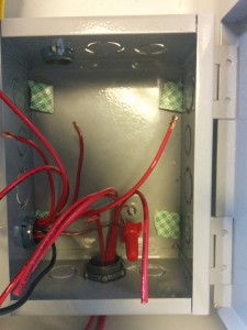
Box screwed down to cooler bottom with tape above each screw. Note the ground wire connected to the box.

Junction Box Wiring

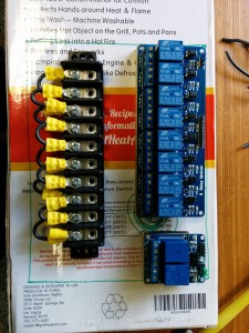
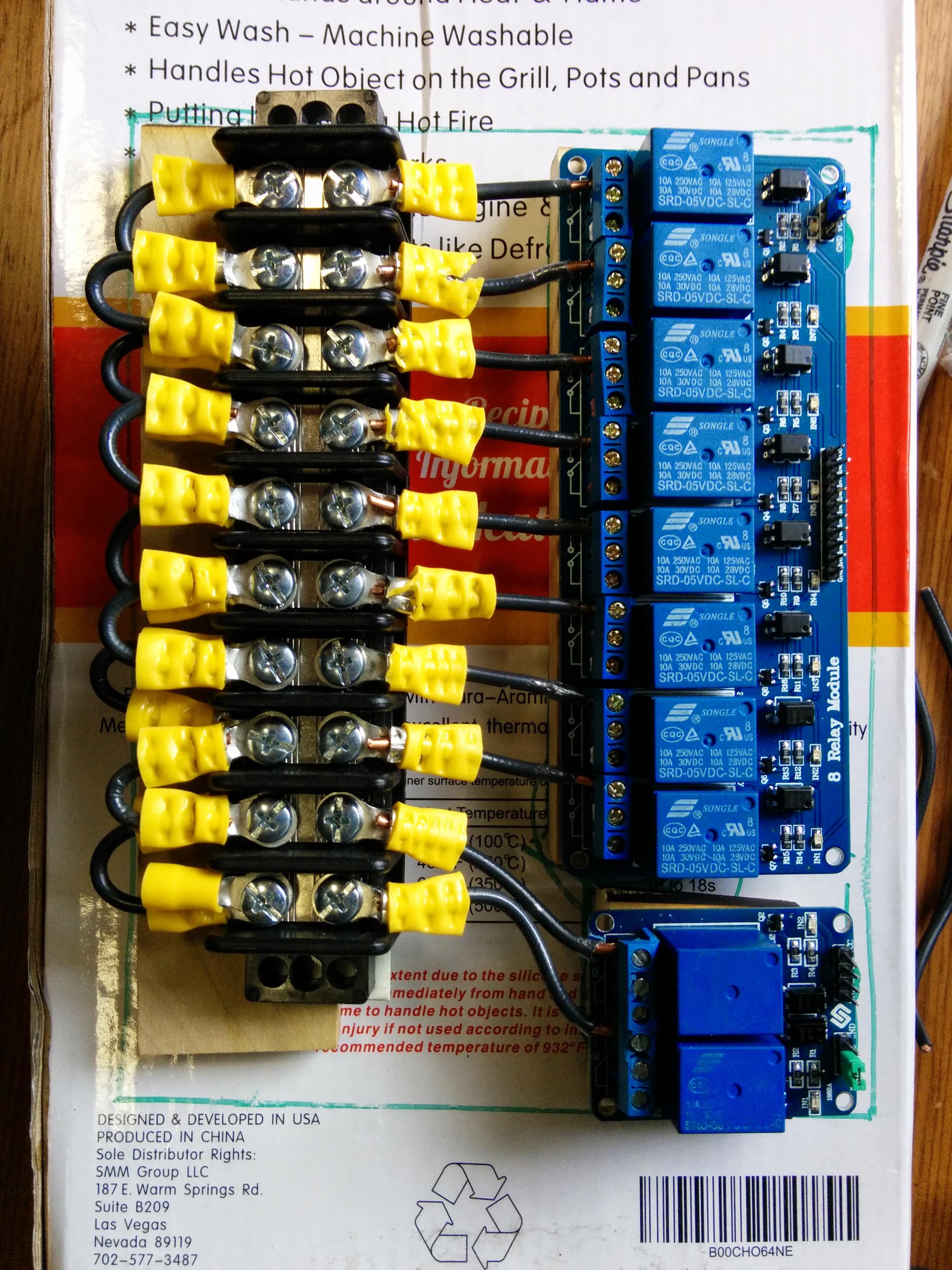
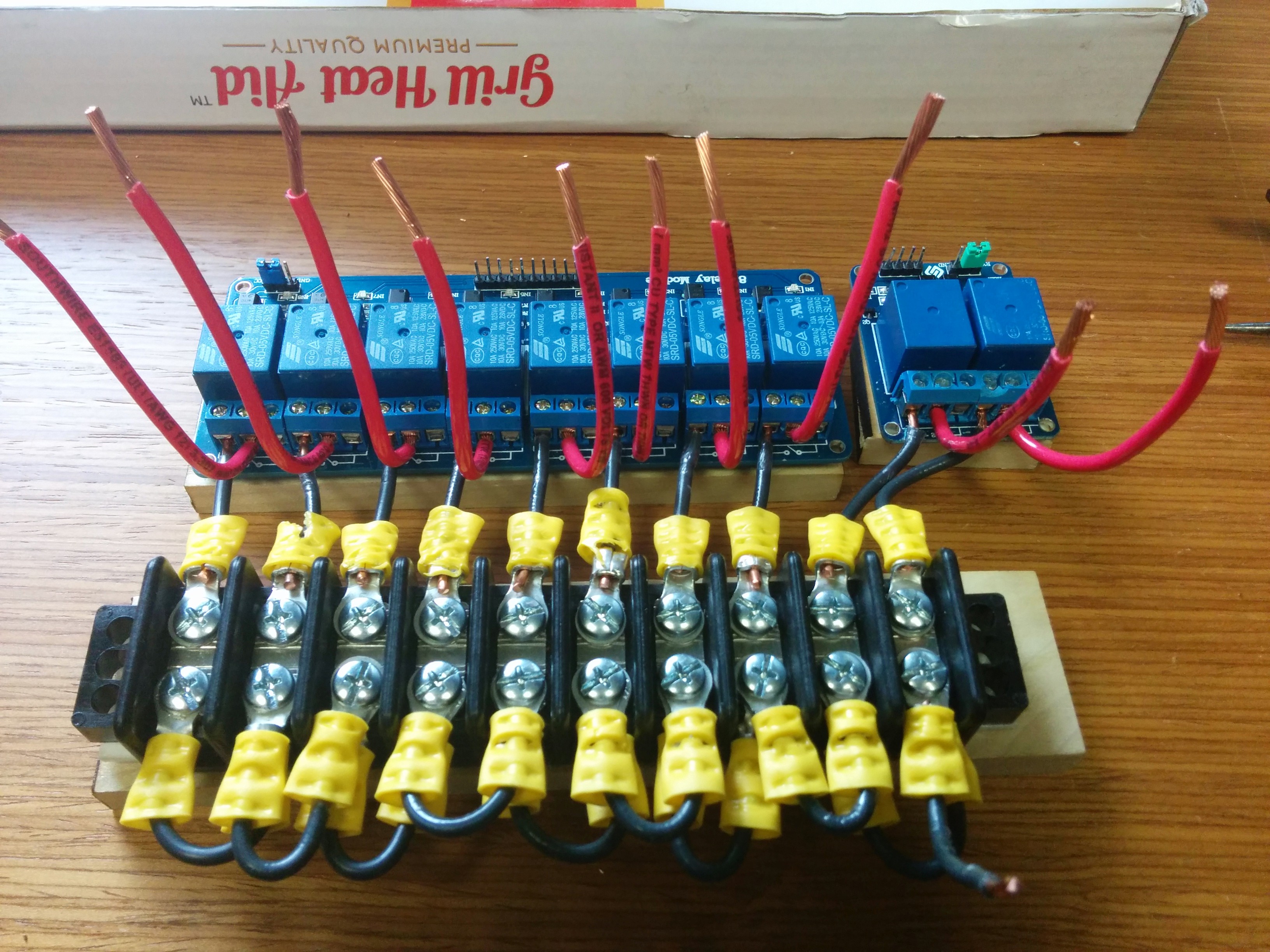
This was probably the trickiest part of the entire build: Wiring up the relays and the bus terminal block and mounting them inside the junction box IN THE BOTTOM OF A COOLER.

Basically a bus terminal block is just a way to connect heavy gauge wire together:
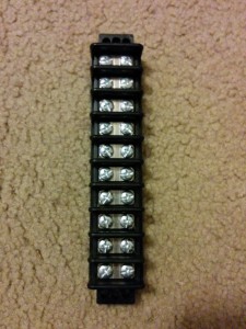
IMG_20150416_194046

bus terminal block

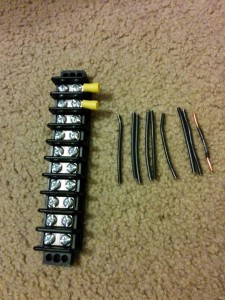
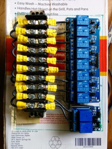
By using short U-shaped pieces of the hot (black) wire and ring terminal connectors, I was able to use the bus terminal block to help connect the line hot wire to the Normally Open (NO) side of the 10 relays.

IMG_20150416_195103 IMG_20150430_111641 IMG_20150502_115121

Given the fact that I had already mounted the junction box into the cooler, I made a template out of a old box that had the same dimensions of the interior of the box to permit doing most of the the wiring in a more comfortable way.

IMG_20150504_125759

Green line here is the limits of the inside of the junction box.

It was a good thing too that I didn’t have a single x10 relay board– as the junction box has a big bump around the ground screw.  So the break between the x2 and x8 relay boards helped to accommodate this bump.

IMG_20150504_135200

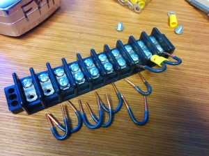
Each of these placed on a block of wood to provide stability and isolation from ground.

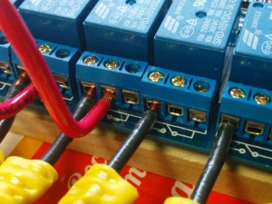
Given that #12 Romex is very stiff, this was the best way to ensure that the final assembly would in fact fit into the box.   Although, if I had to do it over again, I would probably have used a smaller gauge wire, as with #12 it was very difficult to interface with the relay terminal blocks.  I had to ‘encourage’ them to connect.

IMG_20150506_120019

Get in there…

IMG_20150506_191449

What happens when you force 12-gauge Romex into relay terminal block. This board had to be replaced.
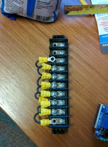
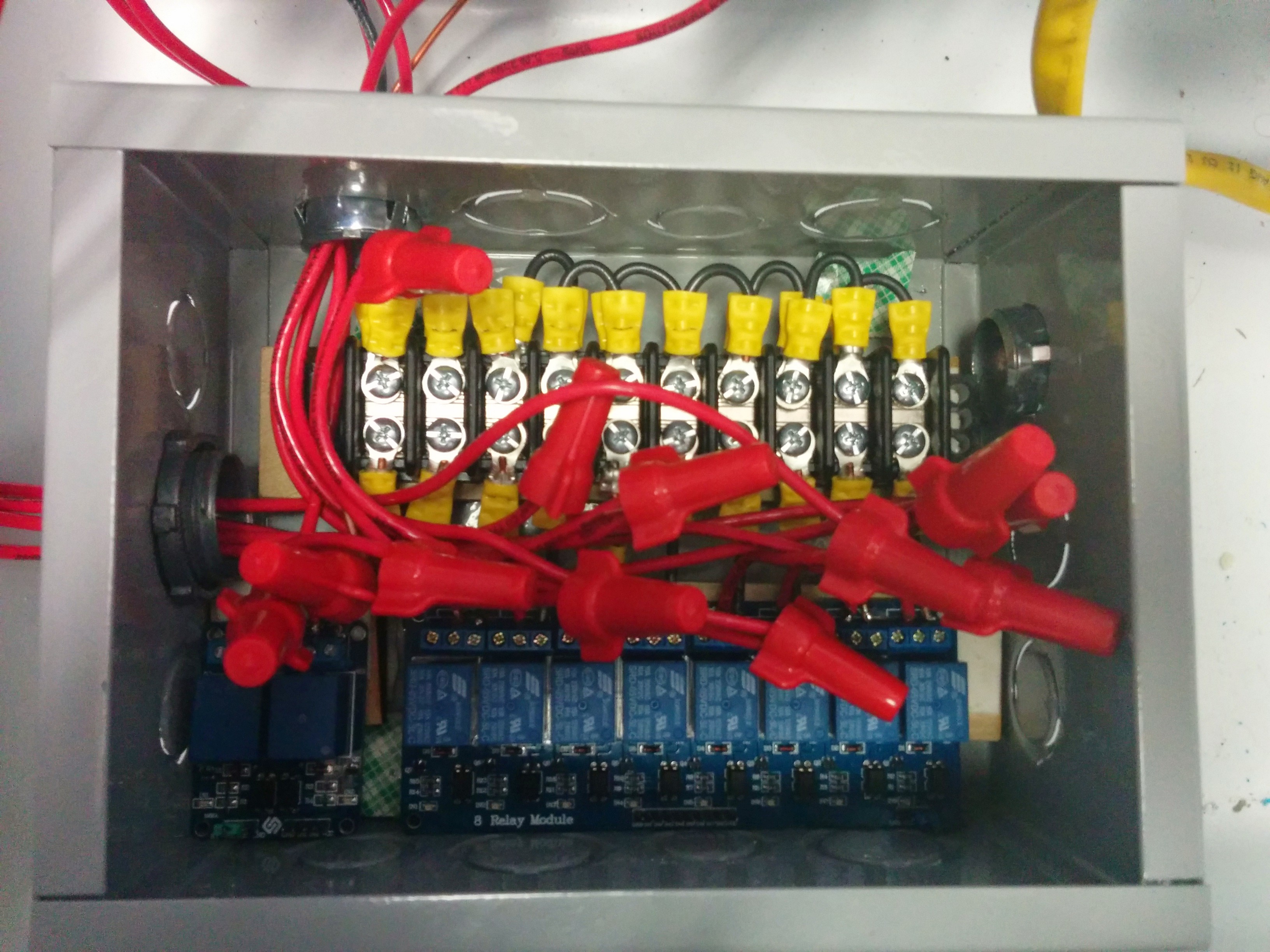
IMG_20150506_121357

Finally done!

IMG_20150506_163110

Double-sided tape added!

By the way, color coding when working with AC circuits is VERY important: Black connects to black, red to red, ground to ground.
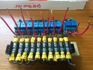
IMG_20150506_165335

Perfect fit!

IMG_20150506_165806

Not bad!

Enclosing

Now that the AC wiring was done, the next step was to enclose all AC circuitry to prevent accidental mishaps.

(Well, in reality the next step was testing all the connections with an ohmmeter, of course without connecting the AC!  This should be done at ALL stages of the AC wiring).

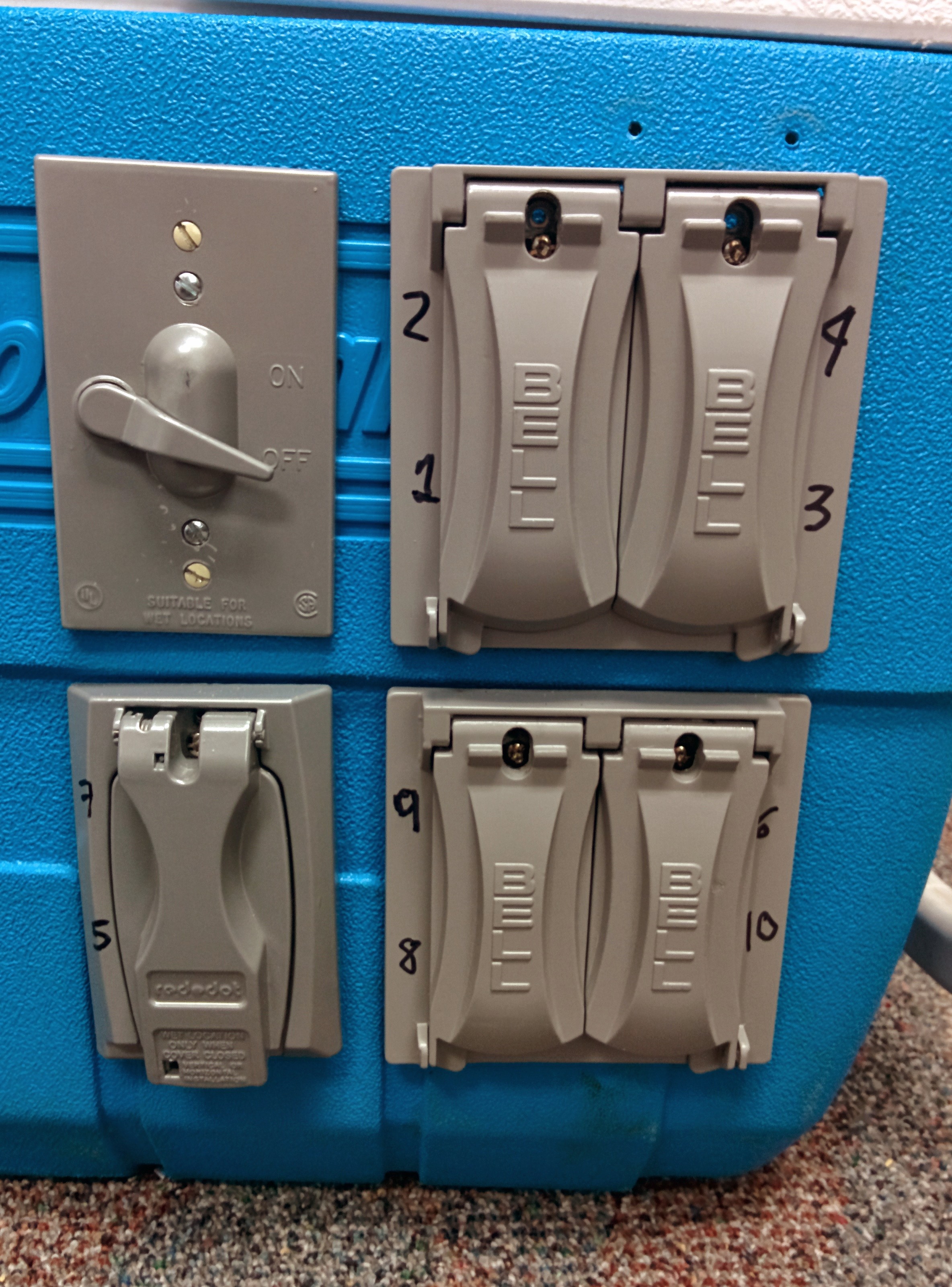
To enclose the exterior outlets and light switch, we decided to add weatherproof covers.  These were readily available at the hardware store.

IMG_20150504_125804

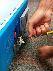
Andres clipping excess metal to add the switch cover.


IMG_20150526_112241

Outlet and switch covers added

Note that we still need to caulk the gap (like you would at your house) around these enclosures if we truly want the Cooler to be waterproof.  The covers were numbered with which relay they were connected.  I cared more about the relay order being numbered sequentially than the outlets.

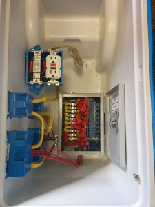
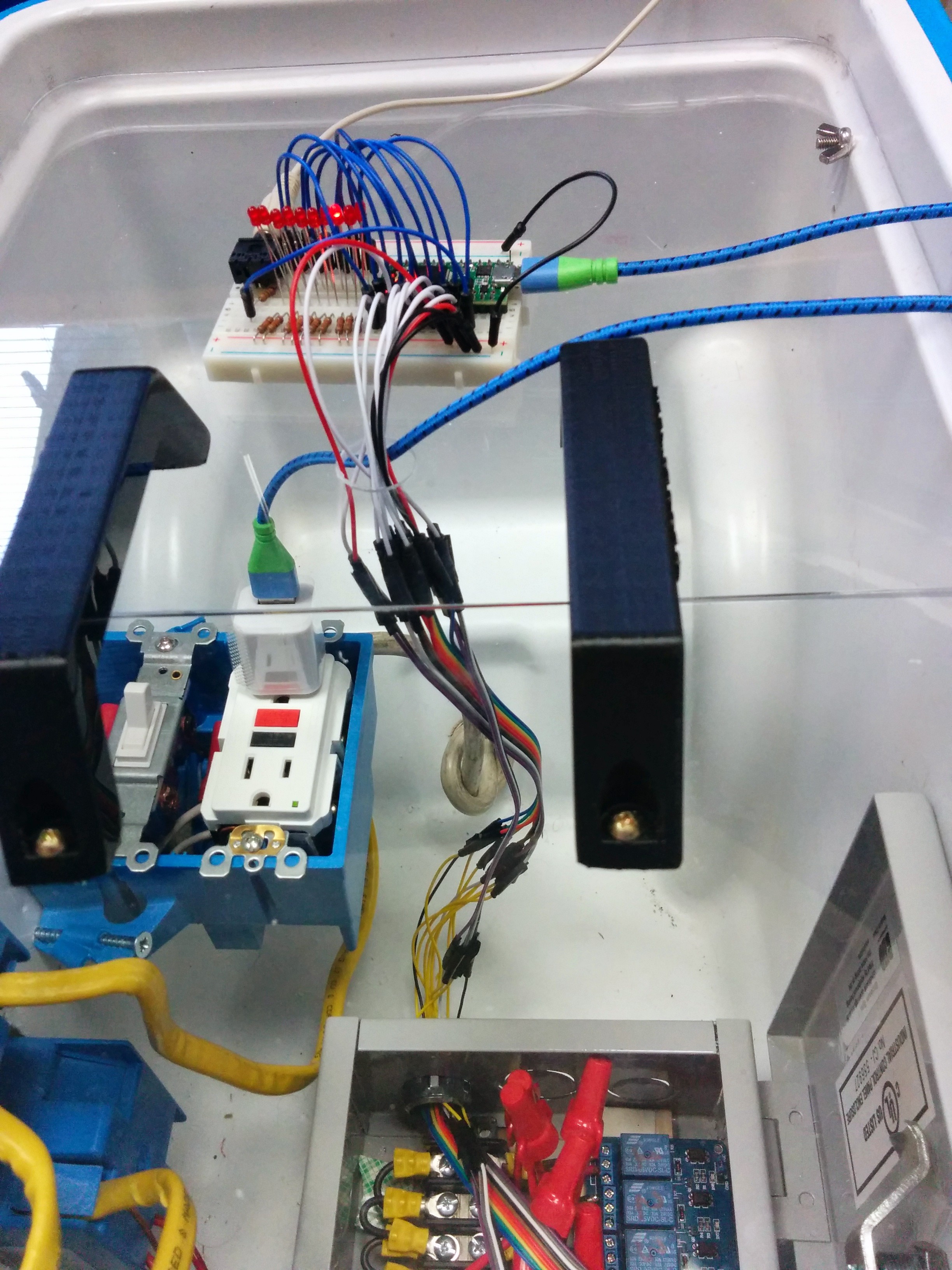
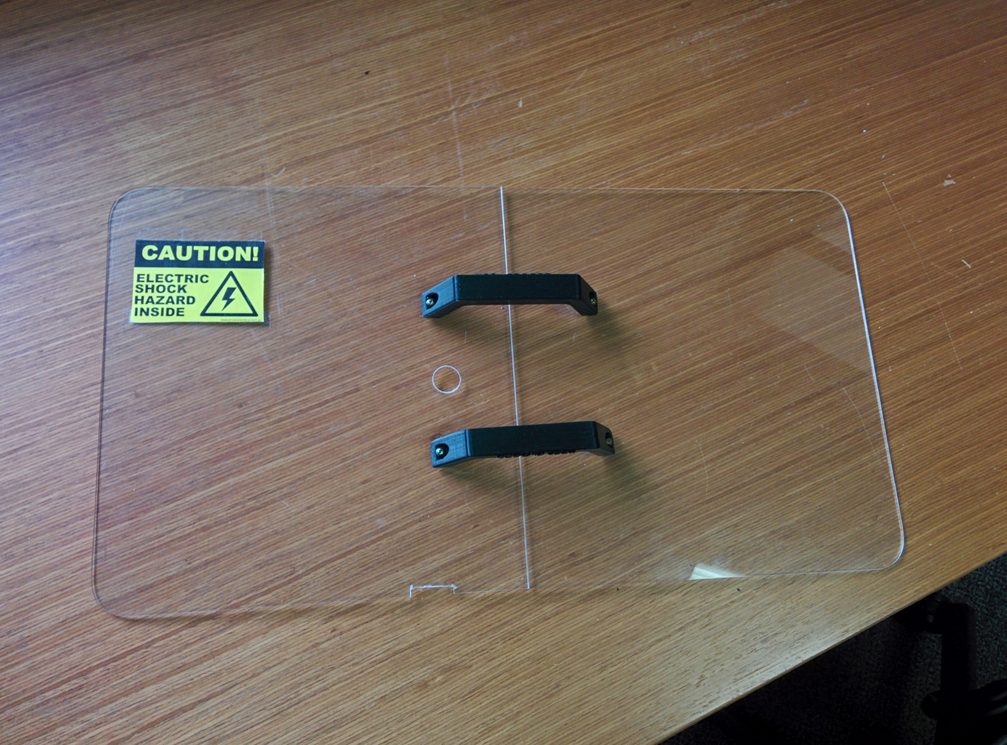
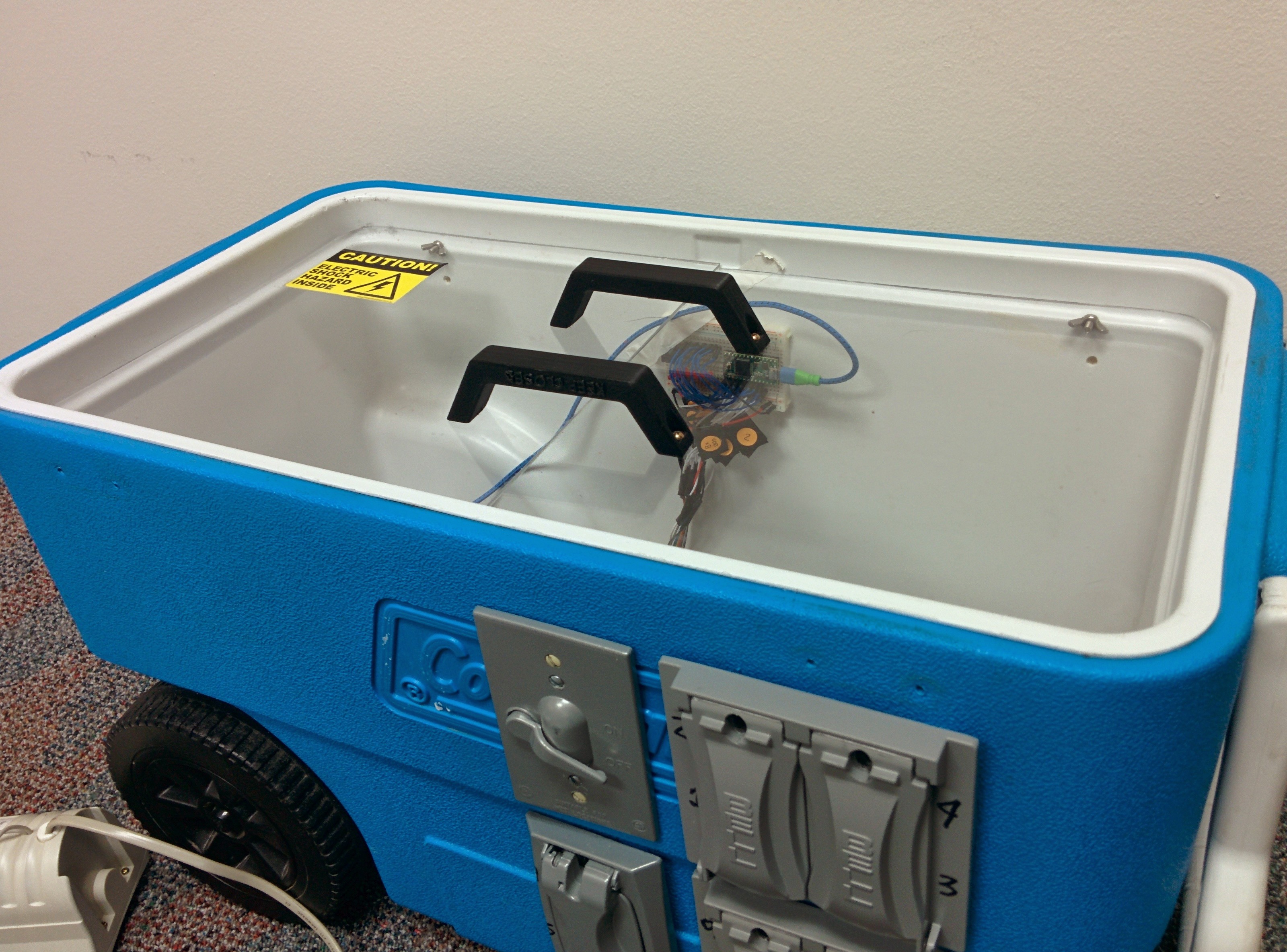
The next step for safety was to enclose the entire interior of the cooler with an acrylic “lid”, so the curious could still view the interior, but do so safely.  The idea was that all AC circuitry would be below the lid, and all DC or microelectronics and prototyping related stuff would be sitting on the lid like a shelf.

The cooler provides a nice lip around the top of the inside where the lid/shelf fits and since it’s very thin doesn’t interfere with placing the Cooler top/lid in place.   The Cooler lid actually has a large interior as well so you can still fit several inches worth of stuff on the acrylic lid/shelf.

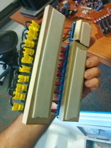
In order to fit the hole exactly, we used a laser cutter to round off the corners.    Cardboard test pieces (not shown) were put into the laser cutter until we got the corner exactly right then the same design was reused on the acrylic.   Due to limitations of the interior of the laser cutter, we had to use two separate pieces of acrylic.

To join the two parts of the lid together, two handles were 3-d printed and attached.   Holes were then added where control and other wiring between the AC and DC parts of the system would go.  A notch was added to one side for the power plug for Computer speakers that would be doing the sound.

IMG_20150526_112336

Safety lid

Finally, a warning sticker was added to indicate the dangerous nature of what was beneath.

IMG_20150526_112354

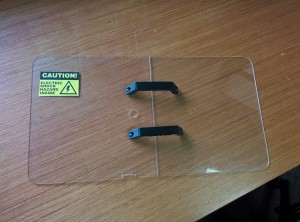
Safety lid with warning

IMG_20150526_112417

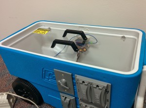
Safety lid in place in Cooler.


Now we just needed to hook up the microcontroller to the relays to control the lights, and to the speakers to make sound!

Stay tuned for Part 2 of this article!!
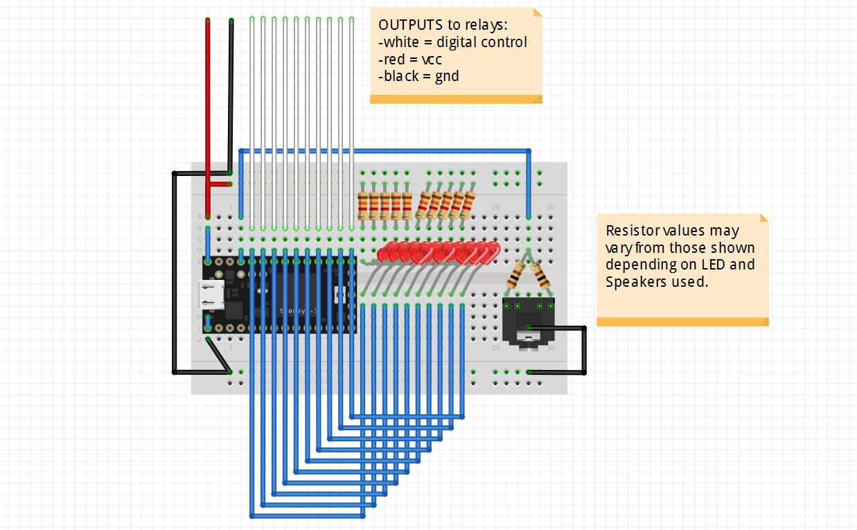


Teensy Music!

Finally got Music and Lights program previously working on Arduino Uno ported over to the Teensy 3.1!

(Did this the night before the SuperBowl, so had the NFL on the brain).

The Teensy supports an add-on to the Arduino IDE (software editor) called Teensyduino.  This permits taking the same Arduino sketches and using them on the Teensy, in theory with no modifications!

Well in reality I did have to make a few updates to the code to get the same Arduino code to work on the Teensy, but they were generally very minor.  Here are the 3 changes I had to make:

1. Rename pins.

Pins used for LEDs and the Audio speaker output were renamed.  This just because the LEDs and speaker were simply hooked up to different pins than they were in the Arduino Uno incarnation.

int num_leds = 12; // WRITE HERE TOTAL NUMBER OF LEDS CONNECTED
int speaker_connect = 23; // WRITE HERE WHICH PIN THE SPEAKER IS CONNECTED TO
int leds[] = {22,21,20,19,18,17,16,15,14,13,12,11}; // WRITE HERE WHICH PIN THE LEDS ARE CONNECTED TO: 1, 2, 3, 4, 5 ....

Here is the pinout diagram showing the location of the pins for reference.  The LEDs can be connected to any of the digital pins (in gray, 0 to 23).  The speaker is driven by a PWM output (the ones in the darker pink).


2. Rename note #defines.

#define statements used to represent the musical note values had to be updated as there were conflicts with additional reserved terms in the Teensy core library.  The code already had to account for an Arduino conflict for the A notes, e.g. “A5” had to be renamed “AA5” as “A5” is reserved for port A, pin 5.   But the Teensyduino library also found conflict with C5, B5, etc. so all notes were given the new nomenclature, AAx (Note A), Abx (Note A flat), BBx (Note B), Bbx (Note B flat), etc.  This was an easy rename and maintains backward compatibility if I want to run it again on Arduino.

3. Turn off tone between notes.

The play_note function in my code had to be modified to turn off the tone() applied to a particular pin between notes.  The Arduino Uno library appeared to handle playing tones back to back of different frequencies no problem.  The Teensy required the addition of a noTone() call between notes for the songs to play back reliably.   To debug this I had the program do a musical scale to see what notes were having problems and it seemed to be randomly dependent on how many notes were in a song as to whether a note was played or not.  Definitely signing up on the Teensy forum (http://forum.pjrc.com) was very helpful to resolving this problem.  I also got a hint from the Arduino tone reference documentation on using noTone().  Again, this is backward compatible to running on the Arduino.

Overall I was pretty happy with how I was able to start using the Teensy almost right away with an existing Arduino sketch!

Here is the Sketch if you’re interested to try it:  

Must do more!


O Tannenbaum…

In the spirit of preparation for Christmas, here’s a neat little Christmas project you can easily do with your kids (or your mom-in-law!):

It’s a $8 soldering kit I picked up a month or two ago at Fry’s, the Velleman “3D Xmas Tree” MK130.  Velleman makes lots of these kind of cool little kits.

My mother-in-law inserting the LEDs to her color arrangement preference.

Some assembly tips:

When inserting the LEDs, be sure not to push the all the way in, leave some extra wire out so you can bend them as shown above.

It’s also very important when inserting the LEDs that the cathode (negative) leg of the LED go into the negative hole of the PCB (circuit board).  Here’s a quick reference:

electronics_led_diagram[1]

Do a quick check after all the LEDs are inserted that all of them are oriented properly BEFORE soldering.  If your LEDs dont’ have a flat edge (these don’t) another quick way to double-check is to look inside the “head” of the LED and check that the “bigger” part inside (on the right above) corresponds to the negative side (shown on the PCB with more flat and thicker white).

Same issue with polarity is there for the capacitors.  The caps conveniently have several large “-” signs running down the negative side, which means the other lead needs to go where it says “+” on the PCB.   Be careful also to not insert the capacitors all the way in either, as you need to leave room for bending them down.  Given the “3D” nature of this particular project, having the components not sticking out makes putting together the two PCBs much easier.

Once you have the LEDs where you want them, separate the extra wire on the other side which will serve to hold the LEDs in place while soldering them.  Do the same trick for other components.  I generally wait to clip off the extra wire until I’m absolutely sure that the component is placed properly, as it’s much harder to fix once the leads are shorter!

Finally, be careful when soldering so as to not overheat the PCB causing the pads to lift!  This happened a couple of times to me when making this tree!  Below is an example of lifted pad not from this project, but from a great Adafruit page on common soldering problems (of which I often have many!):

tools_Lifted_Pad[

I was able to find which joints were bad by using the circuit diagram enclosed in the box with the kit.  By figuring which lights worked and which didn’t was able to track the problem down to 2 branches of the circuit.

Capture2

After some tribulation, here is the final result:

Repeat a few more times if desired:


Merry Christmas!