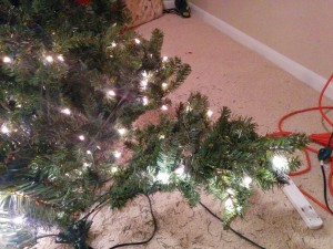
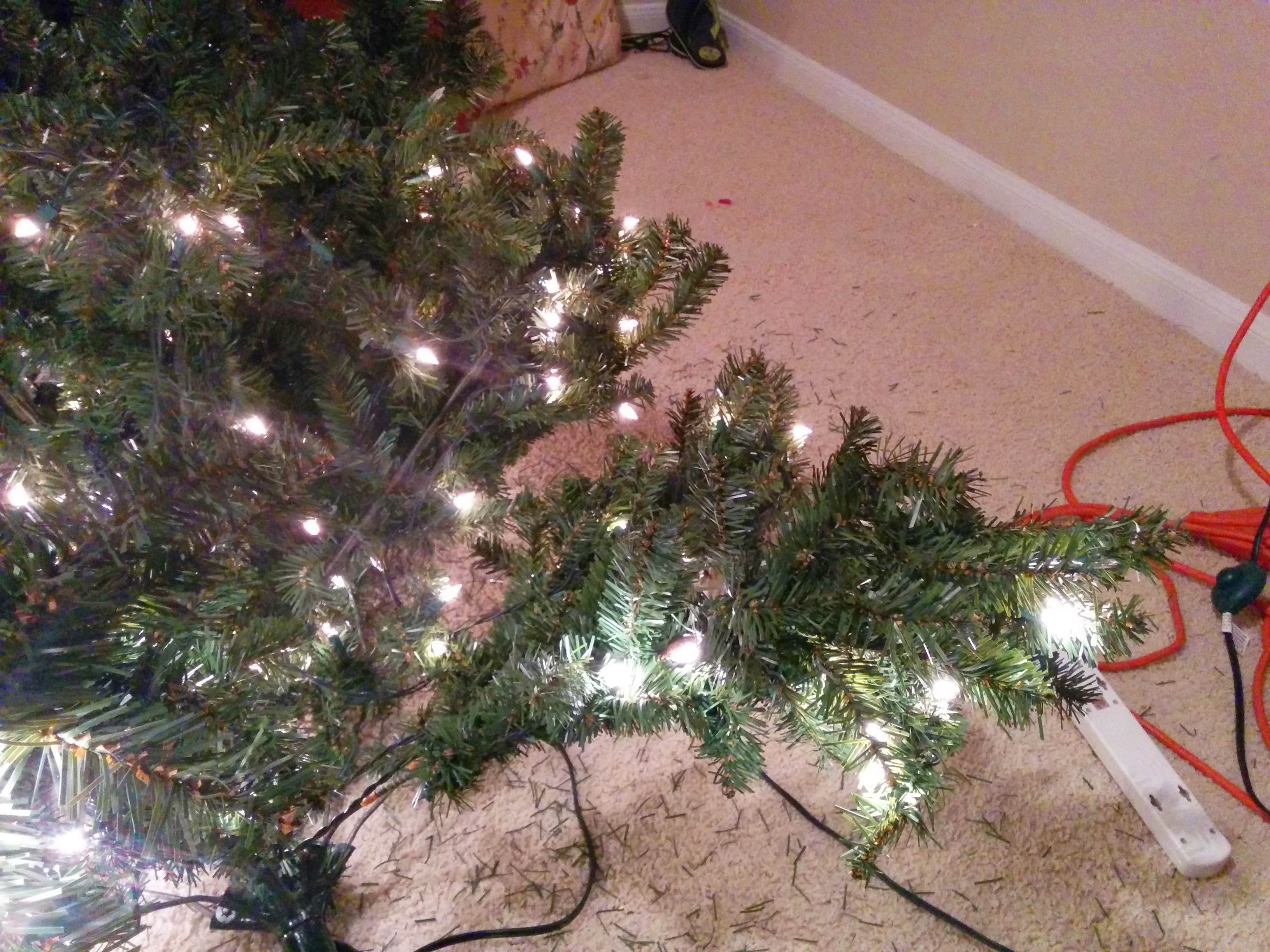
Our pre-lit Christmas tree had slowly degraded after cooking through several Texas summers in our attic. The tree sheds more needles than a real tree and has definitely lost it’s luster.
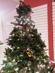
The Horror
The tree comes apart in 3 sections and has 9 strands of lights (50 each). I decided I would try to revive the tree with a cool gadget I spotted at Target, the LightKeeper Pro, that advertises itself as “A Cool Yule Tool”. Hereafter, I will refer to it as my LightSaver Phaser. Or LSP.

It has several cool features to it, including a light tester, a fuse tester, a light puller, an inductive loop to detect current in a live wire, and a way to ‘zap’ a strand of lights either via an empty light socket or by plugging it directly into the plug on the end of the strand. Oh, and the handle serves as a storage compartments for extra bulbs and fuses.
As they say, YMMV (Your Mileage May Vary) and mine certainly did. Of all the features I found the least useful to be the current detector. Maybe it would work great in a standalone string of lights, but with lights on a large tree, with multiple circuit paths and an aluminum frame, I found that the current detector was very unreliable. But before we get to that, let’s do a quick overview of what exactly we mean by ‘fixing’ Christmas lights.
What’s in a light?
Per usual when going to fix something I knew some stuff, but some stuff I had to learn. Of course we all know that mini incandescent Christmas lights are generally connected up in series. But have you ever wondered why when one light goes out the entire string doesn’t go out? If they are in series shouldn’t the entire strand go out?
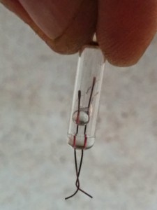
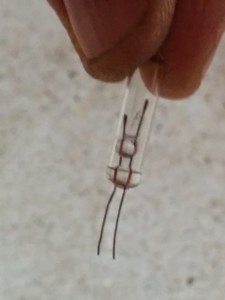
Well, what I learned recently (from a book actually if you can believe that), is that incandescent mini lights, in addition to the filament (what lights up) they also include a “shunt”! A shunt is an alternate path for the current to go in case of filament failure. Here for convenience I’ll reference HowStuffWorks:

Shunt in a mini-light
The shunt is of higher resistance than the filament, so when the filament is intact, the current goes through it and lights the light. When the filament breaks, the current is forced to through the shunt, which is made of a material that will reduce its resistance after a large amount of current goes through it. So even a “dead” bulb helps to keep his brethren “alive”!
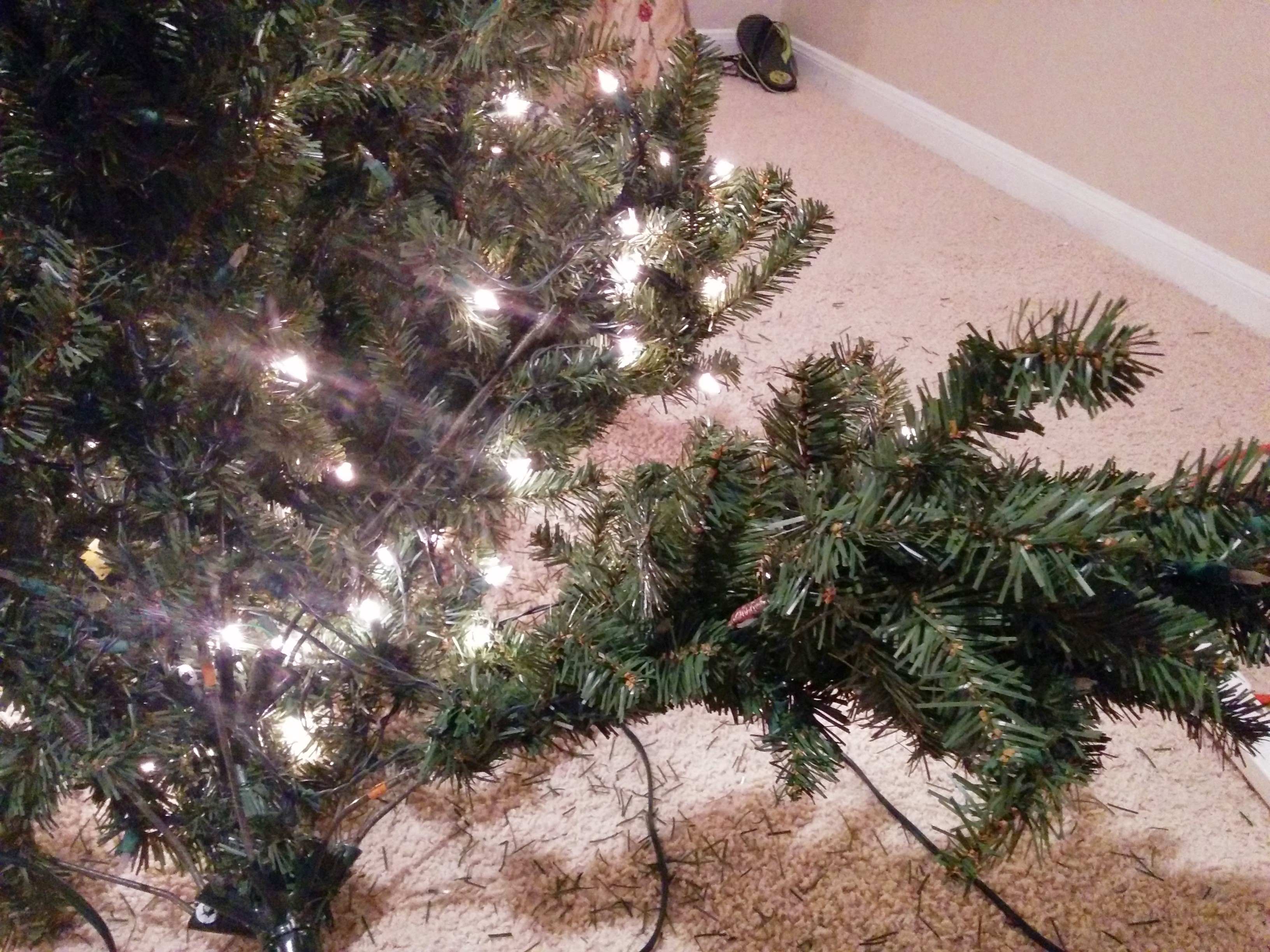
So why the glum tree?
So what is happening in my situation above? Well, if you have an entire strand of lights that still goes out it could be:
- The fuse for that strand is burned out!
- All the lights in that strand are all burned out!
- One or more lights in the strand has burned out but the shunt is still highly resistive.
- One or more lights in the strand has come loose out of its socket not allowing current to conduct (or similar where the legs on a bulb just break).
Well let’s just say that on this tree I encountered all scenarios except for the first one.
Basically, fixing lights means either replacing fuses, replacing bulbs, reseating bulbs, and/or forcing shunts to do their job properly.
Oh, Debug Night…
A quick warning: This sort of debug is very tedious! But if you’re willing to spend a little time and effort, it can be very rewarding, saving you some $$ that could be spent on other things at Christmas!!
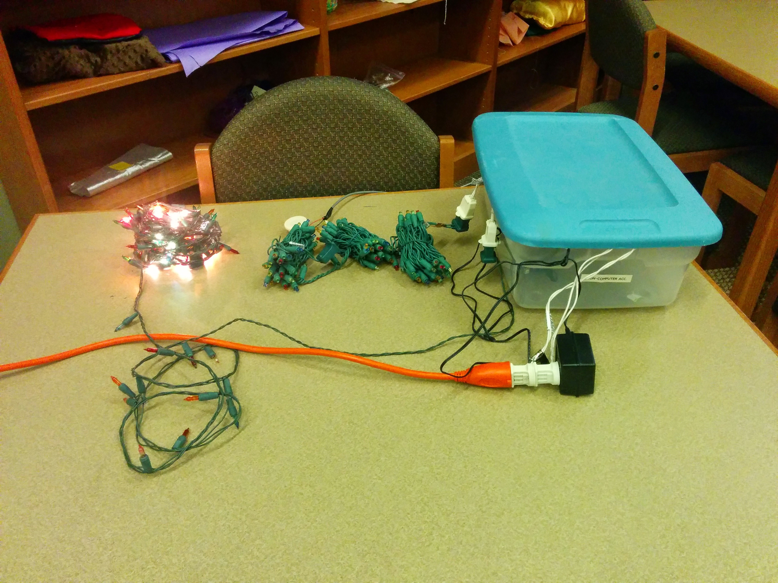
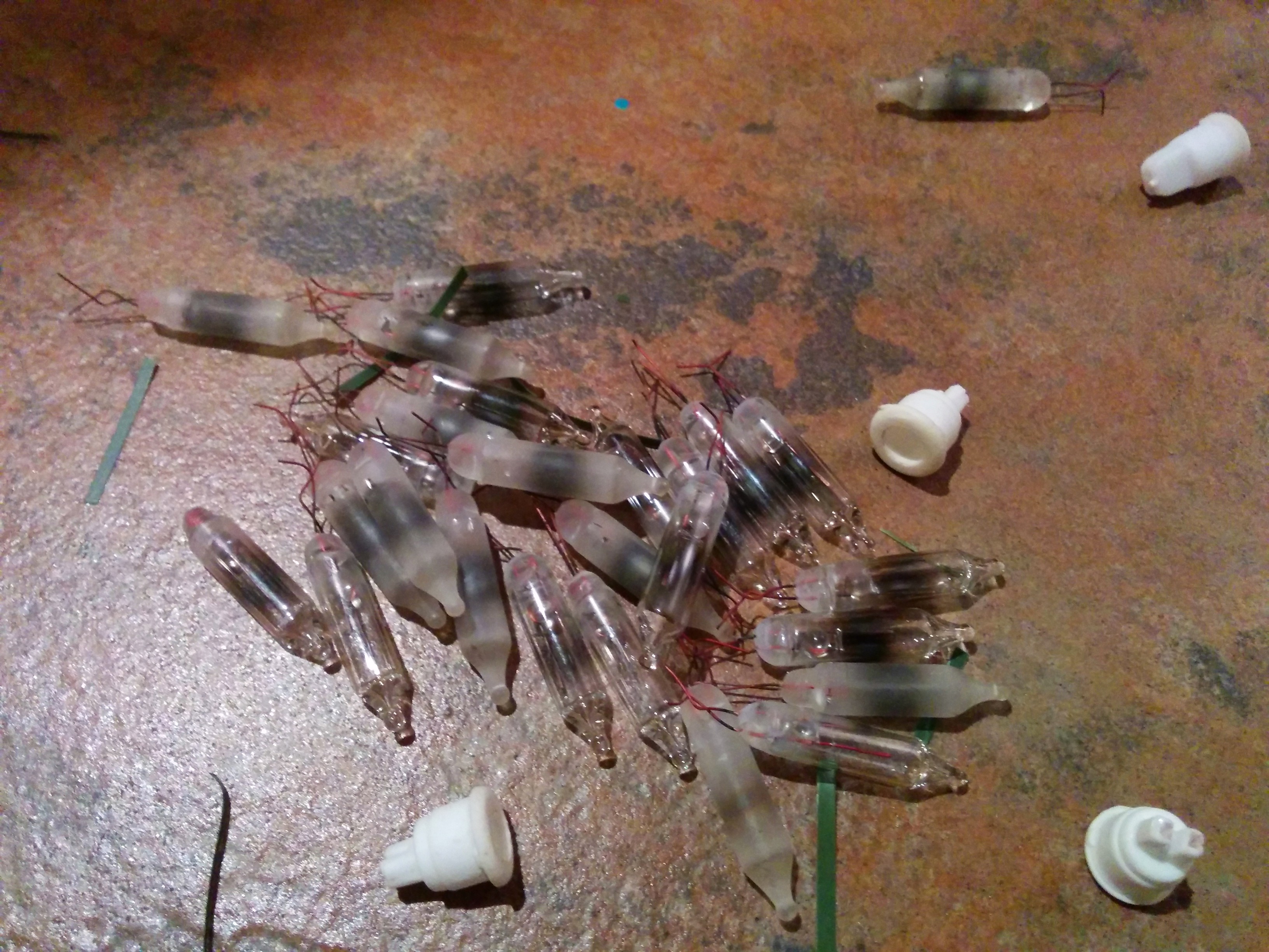
First thing you will need is some spare working lights. The extras that come with a set of lights are generally not enough to repair a completely broken strand on a prelit Christmas tree. Fortunately, I had a spare old strand of lights that I use to scavenge working bulbs.
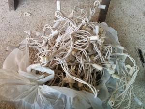
Sacrificial light strand
Check 1: Fuses
The first thing to check is whether an entire strand of lights appears to be out. If so, check the fuses that are inside the socket at the end of a strand:
Go ahead and test the fuses in your handy-dandy fuse tester in your LSP. If any of the lights along that strand are working then it’s definitely not the fuse. Like I said, for me the fuses were never the source of the problem.
Check 2: Zap the Strand Via the Plug
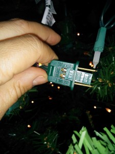
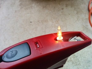
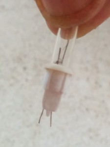
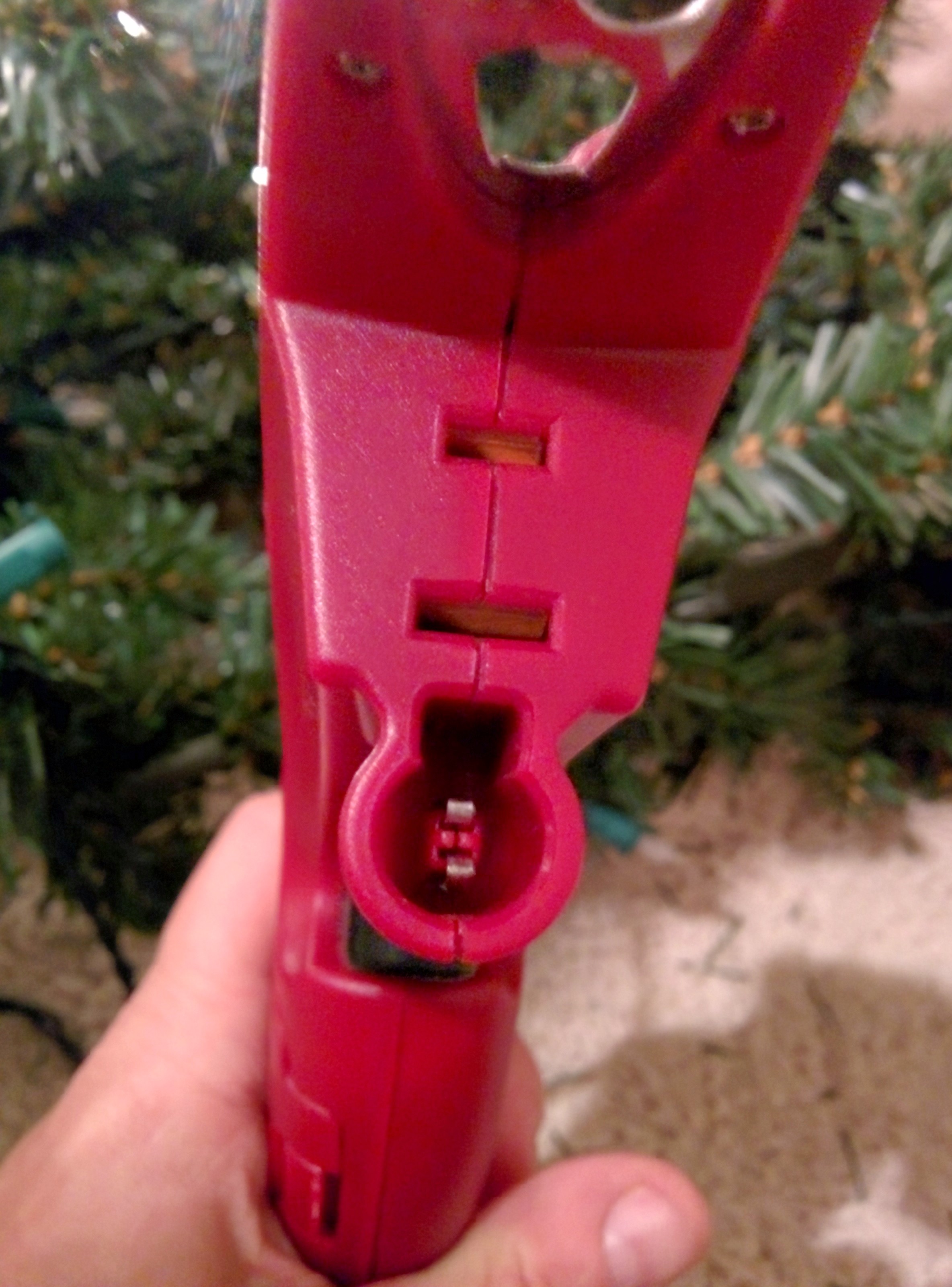
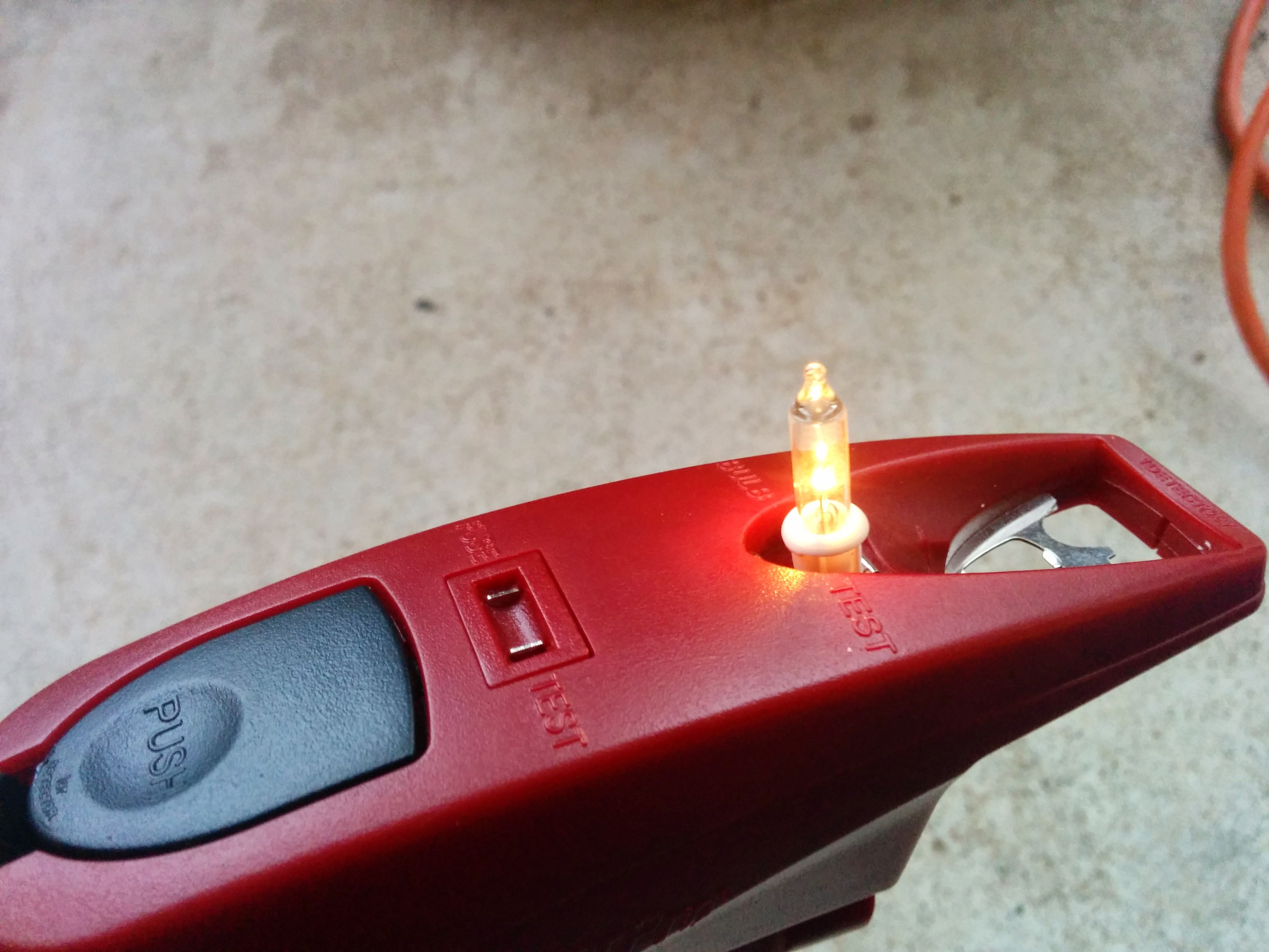
Next thing you can try with is to use your LSP is to zap the dead strands. What this does is to send an extra bit of current down the wire to attempt to improve a shunt that isn’t doing its job very well. First, you can put the plug at the end of a strand into the 2-prong socket on the LSP, shown as 2 horizontal slots below:

LSP plug and light bulb sockets for zapping purposes
Pull the trigger like 20-40 times then check again if any lights recovered. For me this worked to recover some of the lights!
Check 3: Zap the Strand Via an Empty Light Socket
First of all there SHOULD BE NO empty sockets on your tree! Empty sockets cannot conduct current no matter what so be sure you don’t have any!
Alternatively, you can take one of the mini-lights out of its socket and connect the empty bulb socket directly to the LSP, this time with the lights still connected to the household wall socket:

Plugging empty socket into LSP
Again, click the trigger like 20-40 times.
TIP: When pulling lights out on a big Christmas tree it can be really easy to forget where you left that empty socket on the tree which can waste valuable debugging time. Get an ornament or ribbon to remind yourself where you left those pesky empty sockets!
Again, doing this I was able to recover a few more lights:

Check 4: Replace Visibly Bad Bulbs
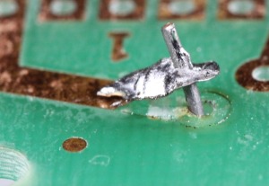
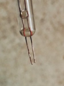
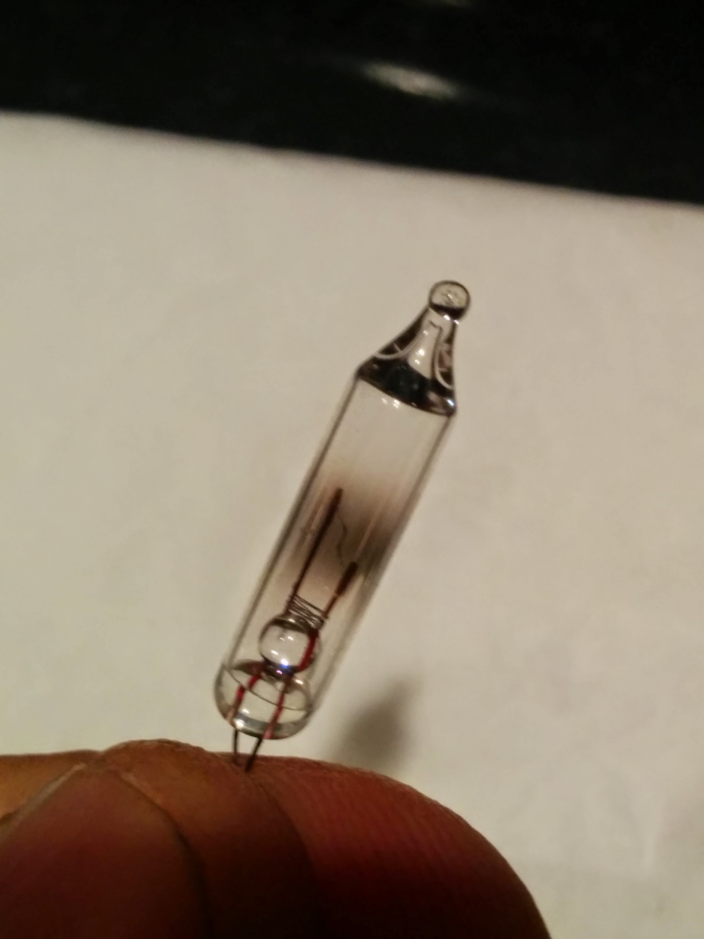
Before getting to the next step, it’s probably best to attempt to find and replace bulbs that are obviously burned out. These you can see have black ‘soot’ on the inside of the center of the bulb:

Visibly bad bulb
Replace as many of these bad bulbs as you can! Test them in the light tester in the LSP after removing them to confirm that they’re dead.
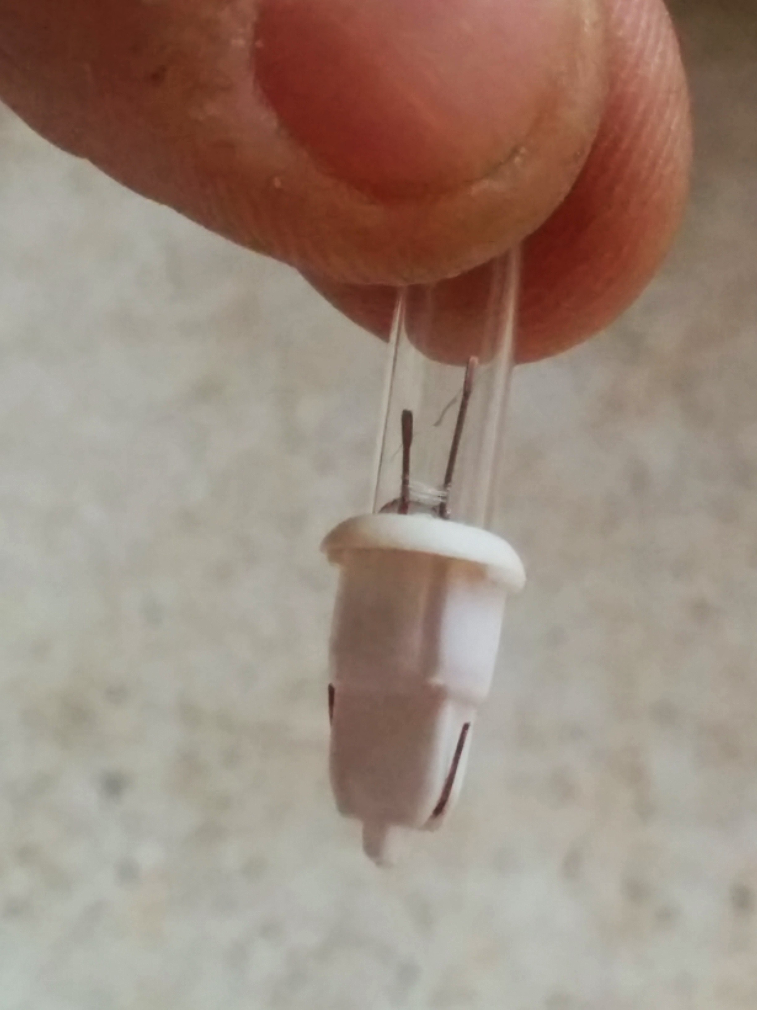
To replace, you’ll need to keep the plastic plug at the base of the bulb and only replace the glass bulb itself as typically the plug and socket have a very tight fit and need to stay together.
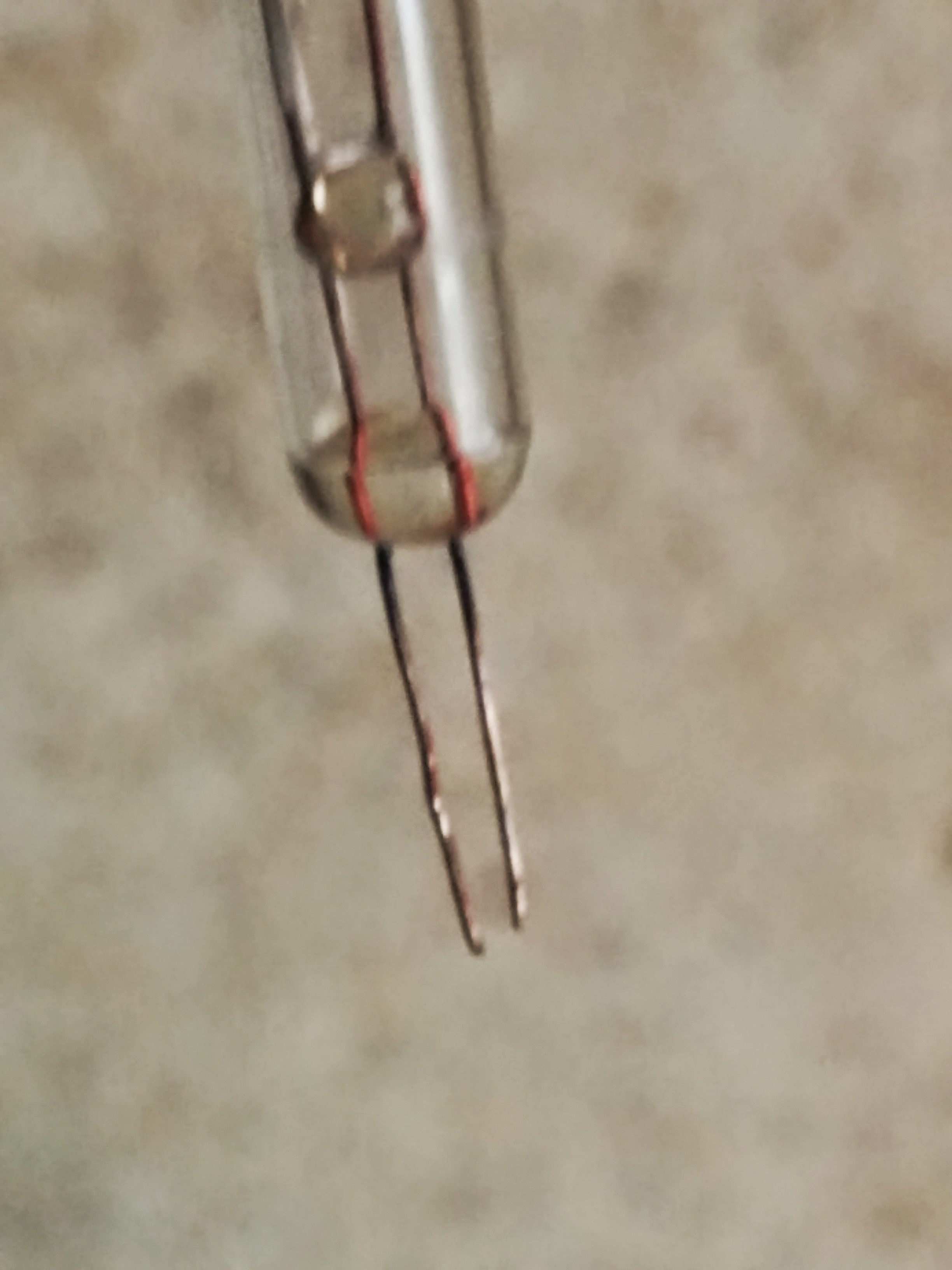
From your sacrificial strand, pull what you think looks like a good bulb:
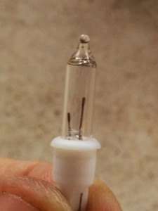
Check the bulb to be sure it’s good before proceeding (no sense in replacing a bad bulb with another bad one!):
Gently bend the metal legs on the outside of the plug downward, and pull the glass bulb out vertically:
Use pliers to straighten the legs:
In doing so, go ahead and scratch up the legs a little with the pliers. This helps to scratch off any rust that may be on the legs:
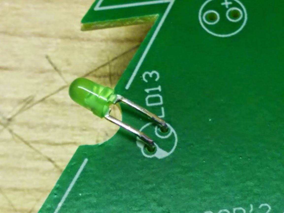
Carefully insert the working bulb into the original plug (from the tree this time) so that the legs each go through their own hole:
Bend the legs back up again:

Finally, test out your new light bulb and plug to be sure it works before replacing into the light socket.
Fair warning: I had to do this at least 50 times for the strand at the very top of the tree, that appeared to have been completely shorted out!

Bring out your dead
Check 5: Find the Bad Shunt
Ok, at this point if you still have lights that appear to be out, especially in large groups and there don’t appear to be any “burned out” bulbs, then we probably have a bad shunt or a bad connection in a socket somewhere.
Finding the culprit bulb after attempting all the above will be tricky and require you to be methodical to keep your sanity.
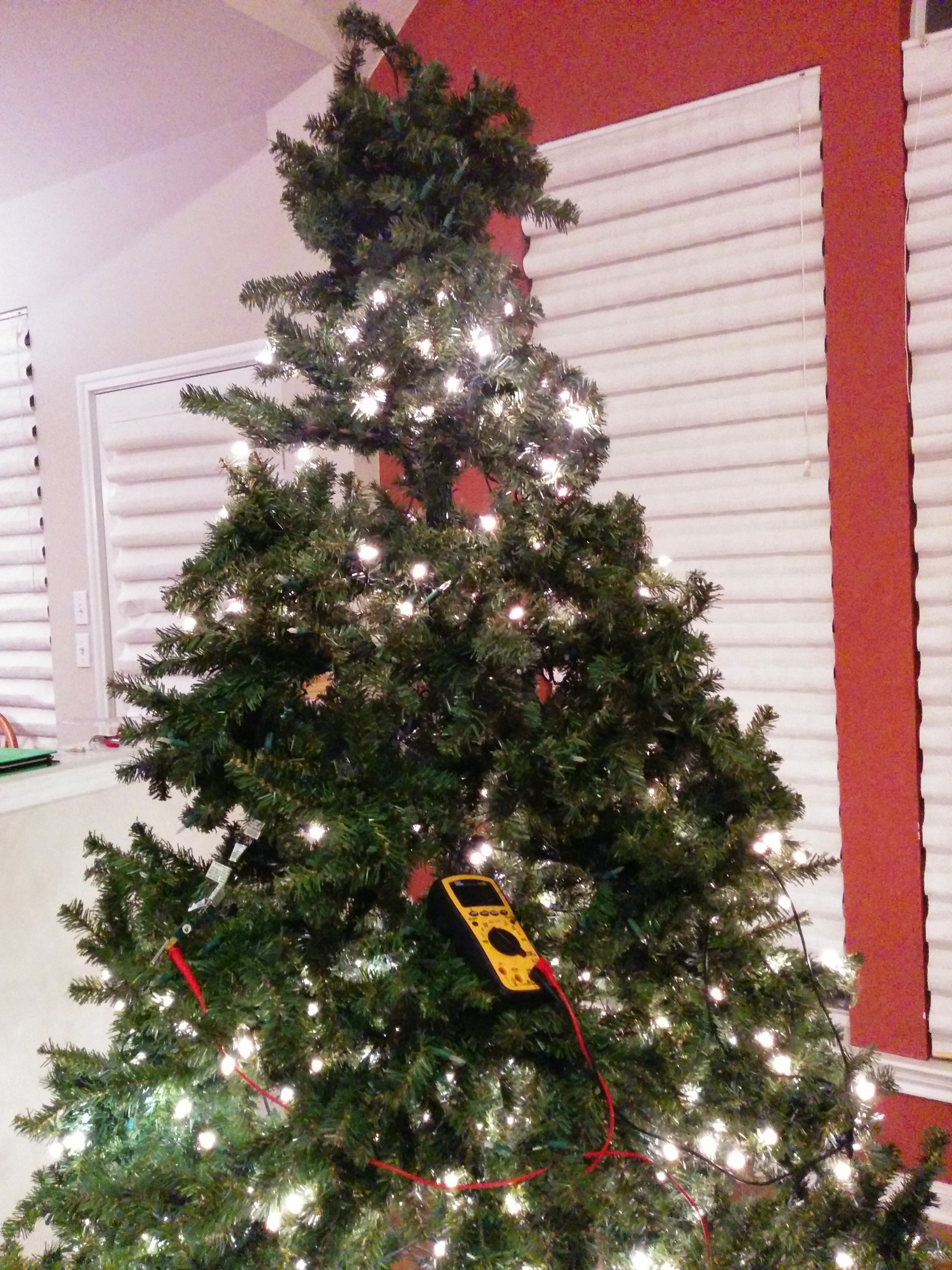
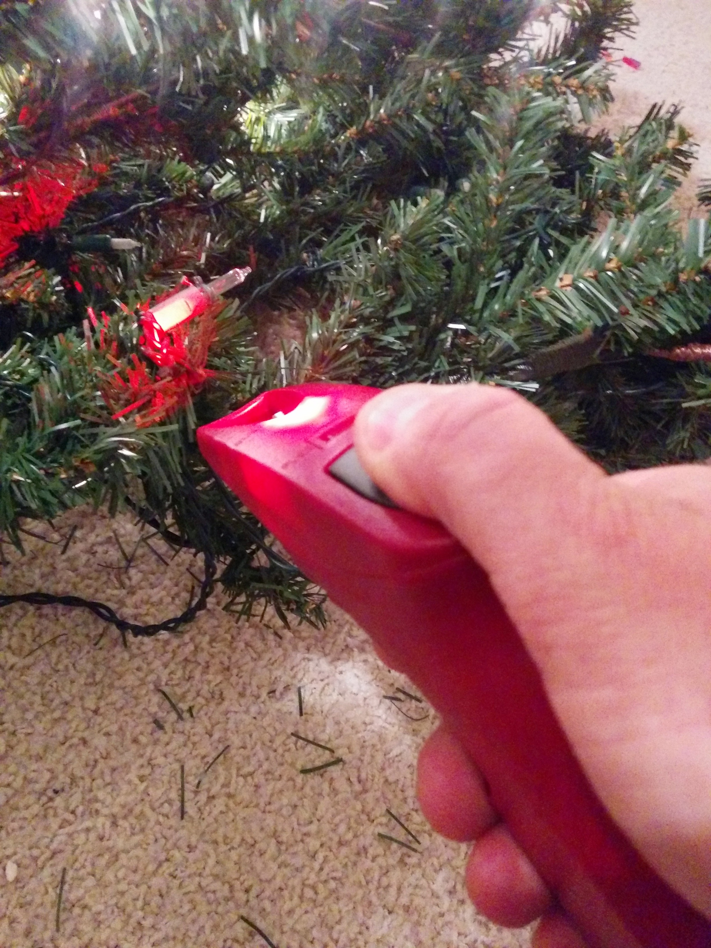
My initial strategy to do this was to use the current detector on the LSP to attempt to find the bad shunt. The current detector is activated by the large black button on top, you point the gun at the sockets you want to test, and if they are receiving current you will hear frequent beeping:
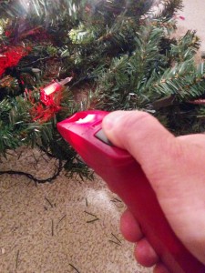
Detecting current.
It lights up a red LED but that has nothing to do with whether current is detected. It’s only there to help you aim the LSP. The beeping (many beeps in a row) are the indicator. You’re supposed to go from one light to the next while the device is beeping until the beeping stops. The socket at which the beeping stopped (or the one before it) is the culprit bulb.
If you suspect a bulb, remove it from its socket, put the LSP on it as before:
If when you put the empty socket onto the LSP, you notice some lights start to come back to life elsewhere on the strand, congratulations! You found a bad bulb with a bad shunt!
However, if when you pull the bulb out BUT BEFORE you put the LSP on it you notice lights GO OUT, bad news, the light bulb you chose, although not working as a light, still has a working shunt! It’s not the culprit bulb!
Like I said before, take the ‘current detector’ with a grain of salt. The instructions say to not touch the tree or wiring while doing current detection. Also it’s possible that the frame of the tree can interfere with the inductive coupling necessary for the detection to even work. So you might sometimes just have to guess.
Take heart, young debugger. You will soon find the culprit bulbs! Eventually, in one particular area I had to resort to marking all “good” bulbs with a permanent marker on the socket so I didn’t go back and suspect bulbs I had already tested!
After a bit of painstaking work, finally found the 2 remaining culprit bulbs and the Ghosts of Christmas Past (as least for now) were banished!

Let there be light!
I truly wish you well on your debugging quest. Please comment if you attempt this little adventure!
After Christmas though, I’ll probably be looking for a new tree– one with LEDs!!


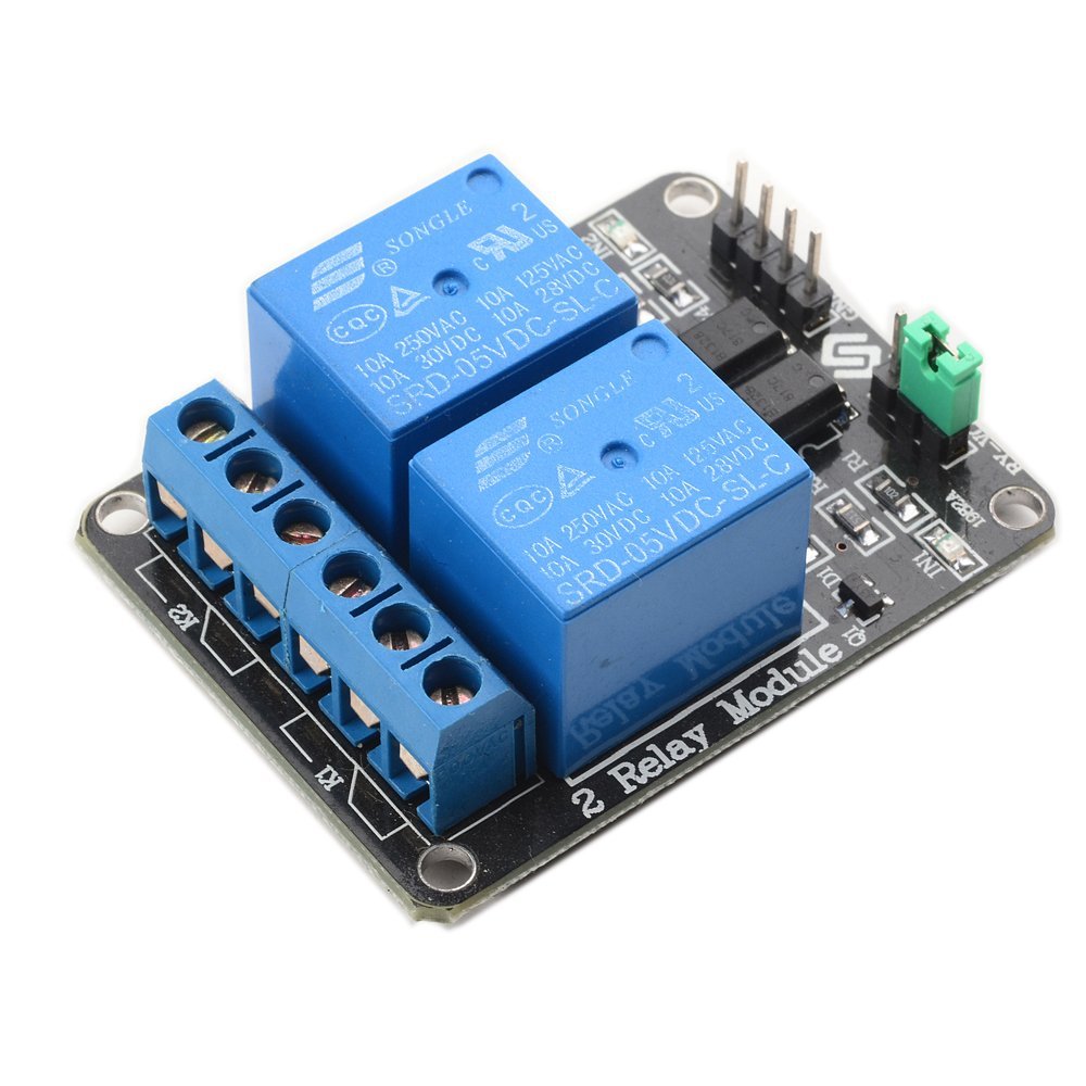 Generally you can use a relay to help you control something high-power or high-voltage like 120V AC electricity with low-voltage, low-power electronics. Relays have been used in everything from cars to sprinkler systems, having started out from the telegraph.
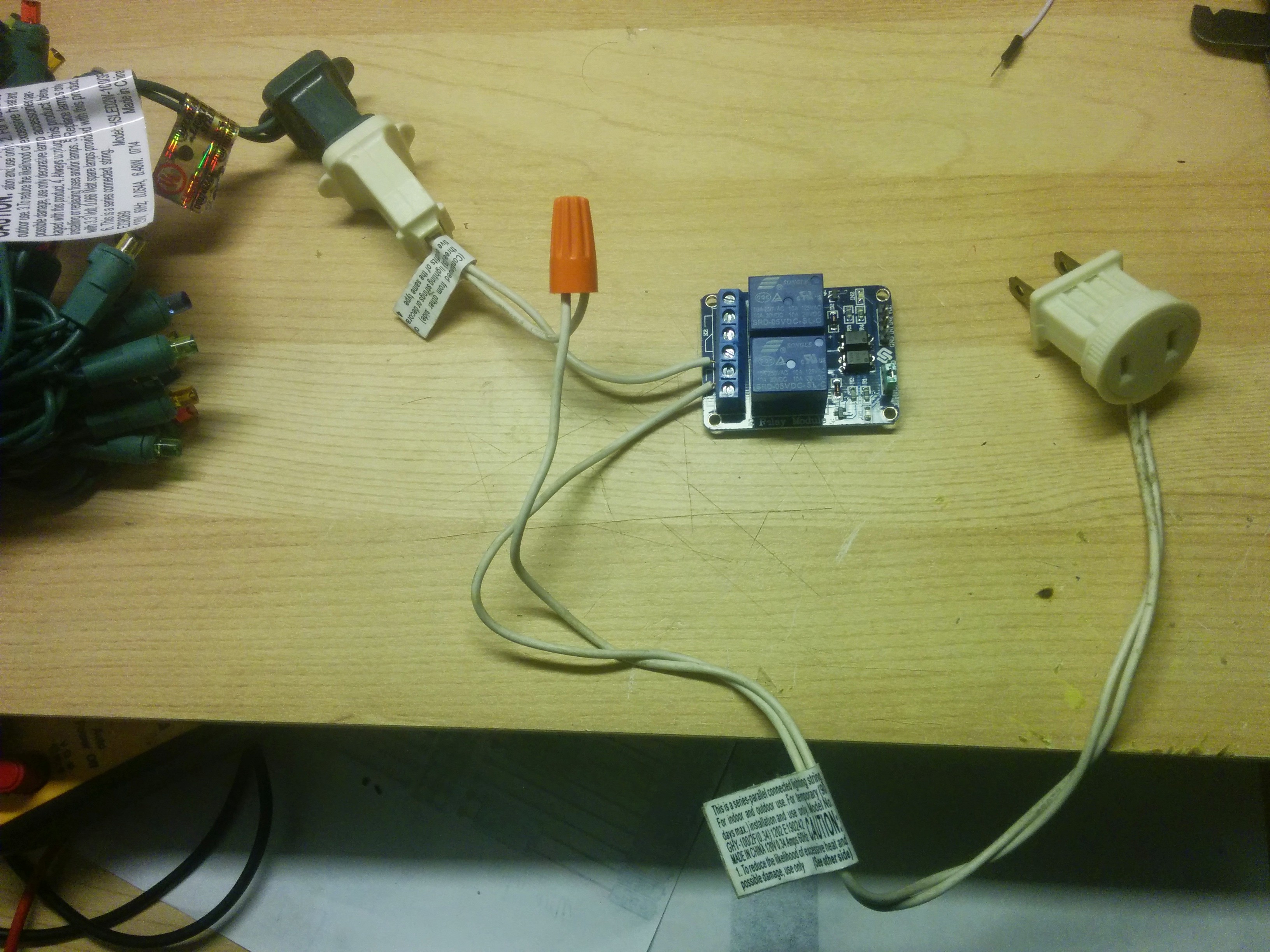
 (Yes, my engineer friends will tell me that if I had connected to the ‘normally closed’ ends of the relay then I probably could have left the drive logic alone, but as a Test Engineer at Freescale who has driven relays in this way for 10+ years, old habits die hard. Besides for safety reasons just felt that lights should be normally off when the system wasn’t powered).
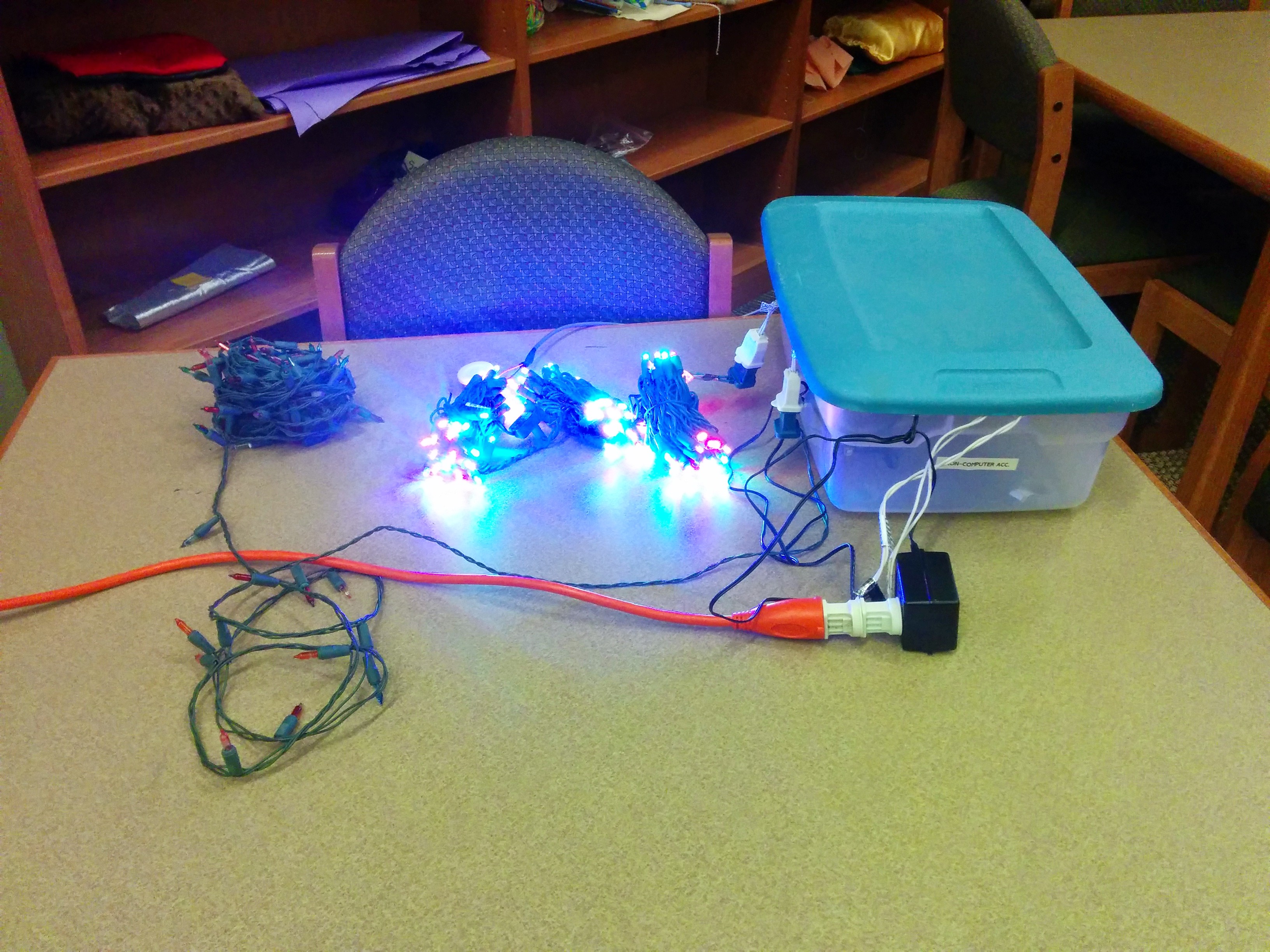


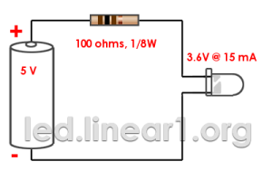


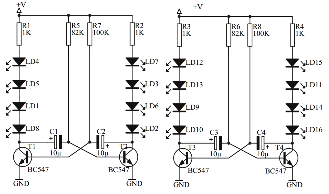
![electronics_led_diagram[1]](http://www.nanowonders.com/wp-content/uploads/2014/11/electronics_led_diagram1-300x194.png)