Welcome to Part 2 of the Magic Cooler project. If you missed Part 1, you can read it here.
Thus far we have focused only on building the AC circuit that will serve to directly control the 10 switchable lights via 10 relays.
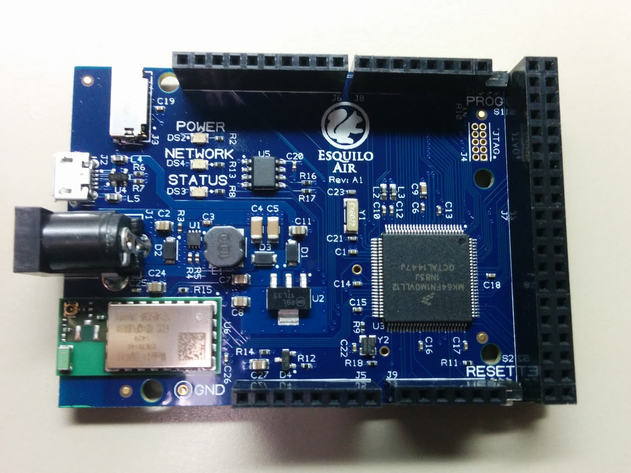
Now, we want to hook up the Teensy 3.1 board to control those relays in time to music, and have the Teensy drive the music itself out to a speaker of some sort. The Teensy 3.1 board uses the Freescale Kinetis K20 microcontoller.
For controlling the relays, I used 10 of the Teensy board GPIOs. These were configured in software to serve as digital outputs. Since the relays used negative logic, i.e. a logic 0 activates the relay, the LEDs on the circuit were set up to also use negative logic so that the same GPIO on the Teensy board activates both an LED and a relay. The LEDs on the circuit protoboard will help in debugging any issues with the relays and give a reminder that the code is running properly. For this project, pins 13-22 were used for LED/relay control. (See the board pinout chart here). Pin 13 also controls an LED directly on the Teensy board– so we have yet another ‘heartbeat’ to remind that the code is running.
The speaker or headphones are connected to one of the PWM-capable outputs of the Teensy. PWM stands for Pulse-Width Modulation and basically is an output signal that looks like a square wave. The Arduino IDE tone() function used in the software permits generating a square wave of variable frequency. When this square wave is applied to a speaker, you get a sound of that frequency! For this project, PWM-capable pin 23 was chosen for sound output.
The diagram below shows how the Teensy protoboard circuit was wired up.
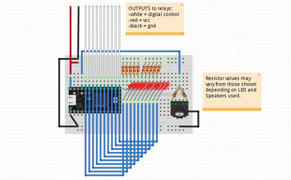
Teensy Circuit Protoboard
Appropriate valued resistors must be chosen for the above circuit depending on the LEDs and speaker used to limit the current through each. For my circuit, I used 1.3k ohm for the LEDs and 100 ohm for each of the 2 ‘channels’ of the headphone jack. 2 different resistors were connected to each of 2 sides of the jack in order to get stereo sound from the computer speakers.
The top of the circuit diagram above shows the 12 wires that will serve to control the relays:
- 10x digital logic control of each relay (white)
- vdd / power (red) (in actuality 2 of these were needed to power the 2 relay boards)
- ground (black) (in actuality 2 of these were needed to ground the 2 relay boards)
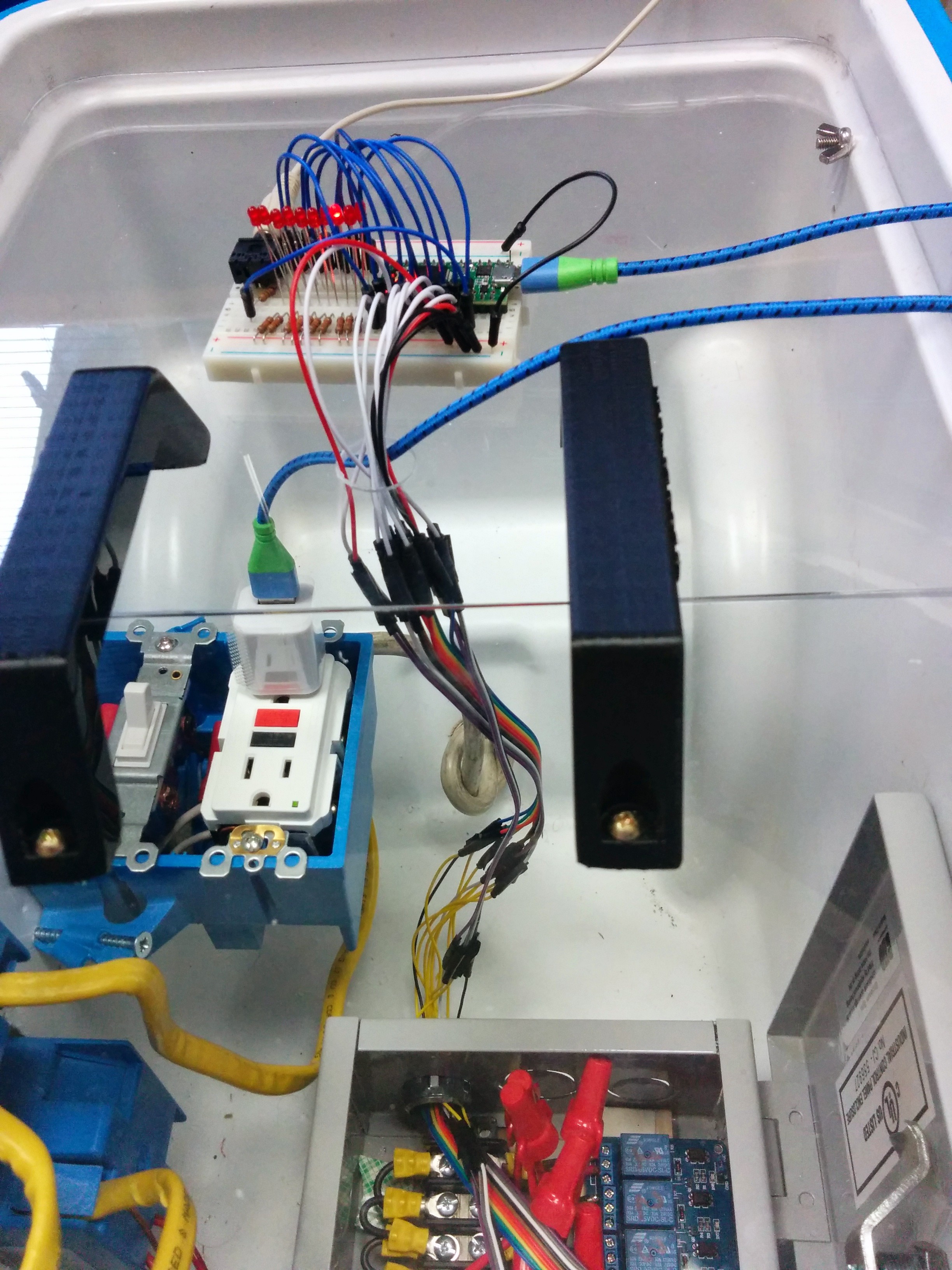
Here is the actual board used:
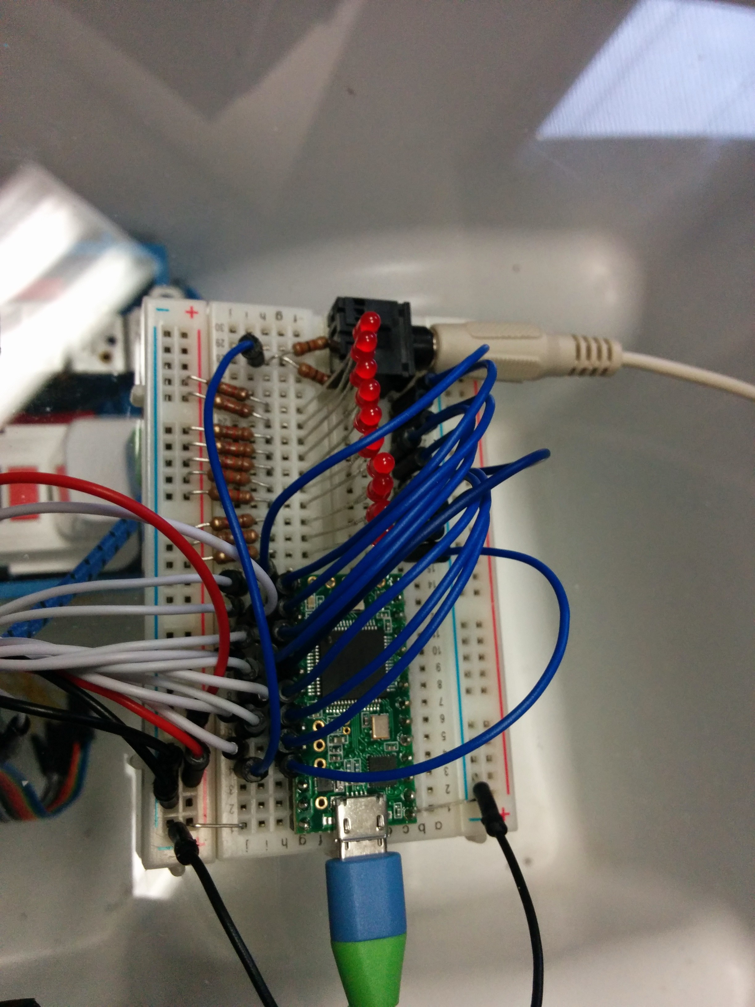
Shown with computer speaker wire connected
The board is powered by a standard micro USB cable connected to a USB AC adapter plugged into the ‘always on’ AC outlet.
Next, we hook up the board to a simple set of computer speakers to make sure it works:
https://www.youtube.com/watch?v=y0DAuEe6r7Q
(In this video you can still see the black speakers we were initially going to use attached to the side of the cooler, but we decided against them at the last minute. Computer speakers worked out just fine.)
The next step was to hook it up to the relay boards! The 14 wires had to be ported through a hole in the clear protective guard then through one of the clamp connector holes in the metal junction box.
Control wires
Once the control wires are in the metal box, they had to be carefully attached to the control, supply and ground pins of the 2 relay boards.
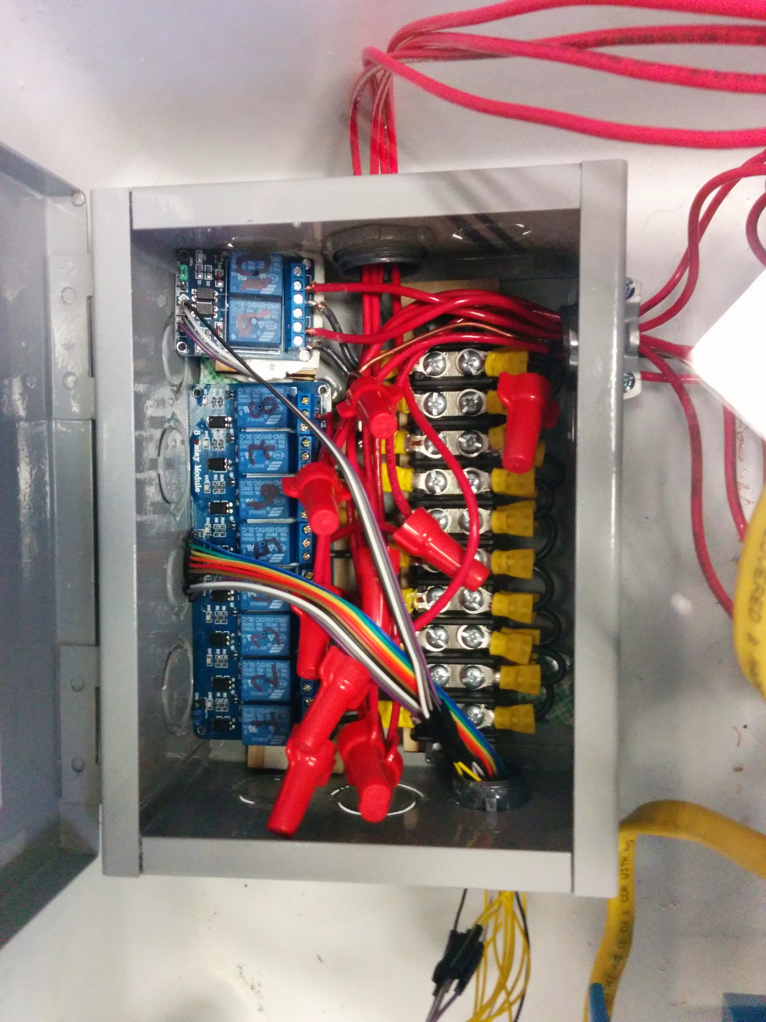
We have control!
Now that everything is wired up, it’s time to run some music and lights!
Here in the Freescale MakeIt Lab we ran a full light test:
https://www.youtube.com/watch?v=20Dsus8Gr4o
(Not shown: One of the ‘songs’ added was a music scale which was a perfect was to test out the lights!)
Stay Tuned for Part3, where we review the software and how easy it is for kids to program it!