


At Austin Maker Faire 2008, I bought a simple board from LadyAda, aka Adafruit Industries, that exhibited Conway’s Game of Life. The so-called ‘Game of Life’ is a zero-player ‘game’ where a 2-dimensional grid with an initial state is defined and then time is allowed to proceed according to certain ‘life rules’. Each LED of a 4×4 grid represents a ‘cell’ and over time either dies, lives or reproduces according to these rules.

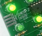
Adafruit “Game of Life” modular board
The board is very well made and designed so that you can interconnect many of these boards together so that you can construct a much larger LED array to make the ‘game’ much more interesting as there are more ‘cells’.
But… I didn’t really have any interest in getting more boards after the first, and the Game of Life really gets boring after a while (to me). So for a while I’ve since been thinking of an alternative use for this little board.
Noticing a binary clock in a coworker’s office the other day I had the idea to reprogram the Game of Life board to be my own binary clock.
Binary Clock
A binary clock is simply a clock that represents the digits of the time in a binary encoded fashion. It’s basically a clock to show off a bit how nerdy you are, that you can read a clock that others possibly can’t.

Binary Coded Decimal Clock
Most Binary Clocks represent each of the 6 decimal digits of the time (HH:MM:SS) with a separate binary value through the on/off state of the LEDs in a column. Technically, this is Binary Coded Decimal format, as each digit in decimal is represented by a separate 4-digit binary number.
In any case, given that the Game of Life board has 16 LEDs, 4 rows of 4 columns each, I could use it to represent HH:MM (no seconds) of the time. I would be wasting 3 of the LEDs of the first digit as it is either 1 or 0 (12hr time notation, 24hr notation it would be 0, 1 or 2 I suppose).
The first job to change the function of the board is to change the program running on the microcontroller. To do that required learning and understanding how to reprogram an AVR-based microcontroller.
Do what?
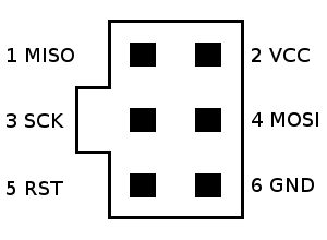
Thankfully, they added a 6-pin ICSP interface on the board.
ICSP stands for In-Circuit Serial Programming and is used to program the memory of a microcontroller while still sitting in the system. (Some micros can only be programmed by being removed from the board and put into a separate, dedicated programmer).
So I added a pin header to the ICSP port on the board and proceeded to figure out how to reprogram using this interface.
AVR programming setup
The microcontroller used on this board is an Atmel Atmega 48V, a little cousin to the Atmega 328P used on the Arduino Uno R3 board. This micro uses the Atmel AVR architecture so it will require an AVR programmer in order to modify the flash program running on the micro.
Looking on Amazon, found an AVR programmer called the USBASP v2.0. Since the programmer uses the 10-pin version of the ICSP interface, so I also had to get a 10- to 6-pin adapter board. Total spent on these: $15 (and can use them for any future AVR programming!).

Ready to reprogram!
NOTE: Be sure when plugging in the 6-pin interface to the board to get the proper orientation as it can be easy to reverse it since the connecter doesn’t enforce it. Check that the GND pin of is on the lower-right as you look at the ICSP port.
NOTE also that I temporarily removed the battery connection from the board as the USB connection will power the board. Will put it back once I’m happy with the final product so it can run standalone.
Next step: writing the new code to load onto the micro and loading it!
Binary Clock Code
Looking online I was able to find the original source for the Game of Life firmware that came preprogrammed on the board on GitHub. This also includes the schematic for the board which will be helpful if I ever want to modify the board in the future. It’s also important when programming a micro to obtain its data sheet so we know how it works. The data sheet for the Atmega48V micro is available from Atmel here.
I started out figuring out how to properly drive the LEDs. The 16 LEDs are directly connected to each of the 8 pins of Ports B and D of the microcontroller. This is the simplest way to drive LEDs from a micro, albeit not the most pin-efficient.
// PORTB = LEDs( 8, 7, 6, 5, 4, 3, 2, 1)
// PORTD = LEDs(16,15,14,13,12,11,10, 9)
Setting a bit to a 1 drives the corresponding output pin high and lights the LED. Setting it to 0 turns off that LED.
For example, these values generate a simple letter D:
PORTB=0b01100000; //60
PORTD=0b11111001; //F9

The plan is to treat each of the columns of LEDs as a value, then encode PORTB and PORTD to properly represent those values.
For this I wrote a small function called display_by_column() that basically takes 4 integers and drives that value in binary on each of the 4 columns of LEDs.
The next step would be to figure out the current time, break that up into 4 digits and send that to display_by_column().
Counting Time
A clock is simply a counter that counts seconds and displays them in a base-60/base-12 kind of way. This “counter” permits any initial value so that you can “set” the clock.
First job was to count seconds. A basic way to do this is to have an infinite loop that increments a 32-bit unsigned integer variable called time with a delay of 1 second per loop (using _delay_ms(1000) ). Since this integer has a maximum value much greater than the number of seconds in a day, a maximum check was added to the code so that at the approppriate time it will roll over back to 1:00.
A second job is to calculate the amount of hours and minutes that have expired based on the current time in seconds.
Third, take the number of minutes and apply modulo 60 so that the value of minutes of 0-59. Do the same for hours using modulo 12 (so that the value is 0-11). Since we measure time in 12-hr format using 1-12 we increment the hours by 1.
Finally, we obtain the 10s and 1s digits for both the hours and minutes so we have 4 values to pass to display_by_column().
This works really well to count the hours and minutes that have elapsed since ‘time began’, starting at 01:00 and going to 12:59, which for this project begins when you plug in the device.
Setting the Time
A proper clock lets you adjust the time to match the current time so that it’s a useful time indicator.
The board already has a switch, so let’s see if we can repurpose it. Looking at the board schematic, this momentary switch is connected to pin PC5, which has dual purpose of PCINT13, or Pin Change Interrupt 13.
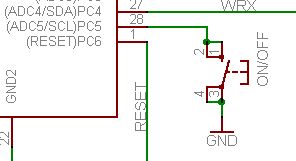
Pin PC5 was already set up in the code as an input via the corresponding data direction register. It was also set up to have an internal pull-up resistor. What that means is that the PC5 input will be high (1) normally, unless the switch is being pushed, in which case PC5 will read as a low (0).
To keep things simple, I added the code that reads PC5 at the start of the infinite loop. If it sees it, it increments the time by 60 seconds. In order that we change the time faster then 1 minute per second, the loop delay is momentarily reduced to 100mS while the switch is being pushed.
Although not using the interrupt, I decided for now this is sufficient for setting the time, since if we increment the time too fast the user may go past their intended time target. If I later add a second switch, I may decide to properly use the external hardware interrupt.
Here is the code for your enjoyment:
AVR Dude!
Last thing is to program the new firmware to the board!
For this I needed 2 things:
- The USBASP driver for use with Windows for the USBASP programmer.
- WinAVR for compiling the code and flashing the device.
WinAVR, pronounced ‘whenever’, is a basic command-line utility that can be used to reprogram firmware onto an AVR processor and can be obtained from http://winavr.sourceforge.net/.
Details on that procedure are here, but basically it uses a special GCC (Gnu GCC compiler) called avr-gcc for the code compilation.
It is critical that the Makefile be updated so that the proper AVR programmer is indicated:
AVRDUDE_PROGRAMMER = usbasp
Finally, just execute the compile and flash to board in one go:
make all
Fin
This was a fun little project for me to help learn a few things about an AVR microcontroller and to repurpose a board that was just gathering dust. Yes, I could have just bought a binary clock from Amazon, but where’s the fun and the learning from that?

BInary Clock indicating: 10:29pm