Here’s another cool Lab that I worked on as part of the edX MOOC I mentioned before using the Texas Instruments TM4C123G Launchpad Eval kit. To learn more details about that course, please see the Lab 10 explanation.
This time in Lab 13 I was tasked with developing a 4-button piano that plays music using 4 momentary switches and a DAC (Digital to Analog Converter) circuit to generate the sound.
(So what happened to Labs 11-12 ? Chapter 11 covered learning to use the UART and the associated lab involved using the UART to talk to the Nokia 5110 84×48 LCD, which was pretty cool. It really was meant more as a stepping stone for later labs that would output to the LCD. Here’s a video of the profs demoing the expectations for Lab 11. Chapter 12 covered learning how interrupts work on the TM4C123GH6PM, and mainly how to use the Systick Timer based periodic interrupt. Lab 12 involved making music using a DAC, similar as Lab 13 below.)
Lab 13 — Making Music
The purpose of this lab was to be able to play 4 different notes, or tones, on a speaker when each of 4 buttons are pushed.
To generate sound, a simple Sine wave was generated by the TI board and sent to a speaker. Although an analog output on the microcontroller could have simply been used to generate this Sine wave, for the purposes of learning, digital outputs of the microcontroller were used instead. These were then fed into a rudimentary DAC (digital-to-analog) circuit on a breadboard to generate the necessary analog Sine wave.
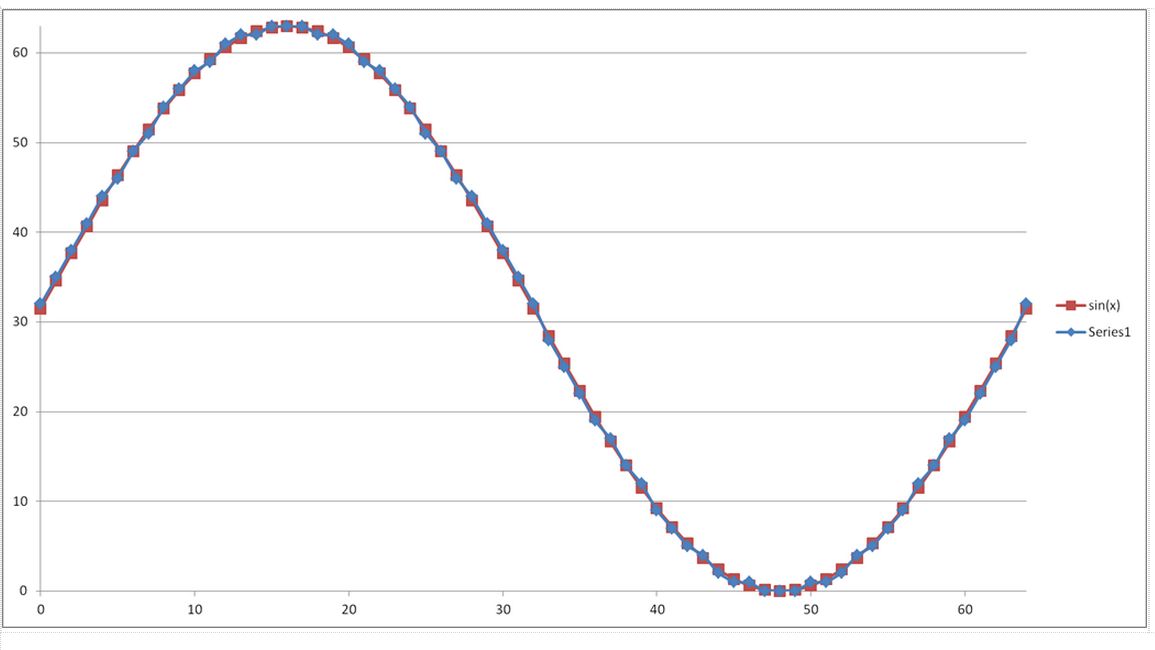
6-bit Sine Wave in Excel
The Sine Wave above is of 6-bit resolution, i.e. it is represented by digital values from 0 to 63 (2^6) in amplitude. As a result, the period, or time scale, of the wave above is also divided to 6-bit resolution.
Basically, at each point in the wave above, a different 6-bit value (0-63) will be driven by the MCU fast enough so that the ear HEARS a continuous Sine wave of a single frequency. Again, there are built-in functions to do this, but for the purposes of learning, this more low-level approach was used.
The Sine Wave above was actually defined first in Excel, just using math:
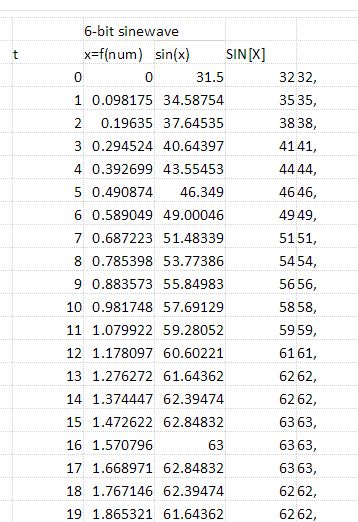
Partial 6-bit Sine Wave Table
Sure this could have been calculated in the code– but pre-calculating the values above and storing them in a table in RAM will save on execution cycles, which for this application is critical in not slowing down the generation of the Sine Wave in real time.
So how exactly do we go from a 6-bit digital signal generated by code to an analog Sine Wave that a speaker will use to generate sound?? We need to build a digital-to-analog converter, a DAC, circuit.
Well, there a few different DAC circuits we could use, and Chapter 13 showed 2 types: 2-bit weighted binary and R2R ladder. Both have the digital outputs drive nodes of a resistor-based circuit organized in such a way so that different digital values driven on these nodes result in different voltages corresponding (in this case) to one of 64 voltage levels generated on an ‘output’ node.
The 2-bit weighted binary resistor circuit looks like this:
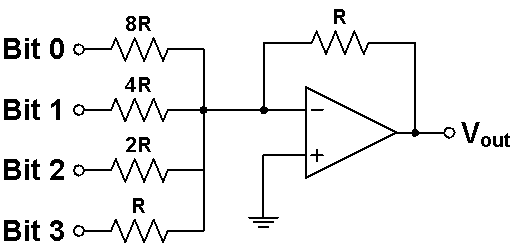
4-bit DAC
The problem with this is that the more bits you add the greater the difference between the resistance on the least significant bit 0 (LSB) and most significant bit 3 (MSB). Resistors have % tolerances so the larger they get the more inaccurate they get. It’s also very difficult to find resistors that match all the values I need (or you have to use resistors in series).
So I decided to use the R2R resistor tree method:
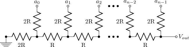
R2R ladder of n-bits
In this DAC circuit, the largest resistor is only 2x that of the smallest one so it’s easier to implement with resistors at hand. Of course, resistance errors still add up along the various current paths, but for me this was the easier circuit to build.
Now the final step is that we need to drive each of the 6 digital outputs fast enough so that it SOUNDS like notes are being played at a particular frequency.
Interrupts
In order to make the DAC sound like it’s playing a single note, the processor has to drive the 6 digital outputs at a frequency 64 times that of the note. Or saying it another way, the period of time between changes on the 6-bit digital output must be 64 times smaller than the period of the note.
The table below shows the required time delay for each digital update in the Period/64 column.
| Piano Key # | Note | Frequency | Period | Period/64 | Systick RELOAD value (80MHz) |
|---|---|---|---|---|---|
| 0 | C | 523.251 Hz | 1.911 mS | 29.861 uS | 2388 |
| 1 | D | 587.330 Hz | 1.703 mS | 26.603 uS | 2127 |
| 2 | E | 659.255 Hz | 1.517 mS | 23.701 uS | 1895 |
| 3 | G | 783.991 Hz | 1.276 mS | 19.930 uS | 1593 |
To achieve this, I used the Systick Timer to drive a periodic interrupt in the microcontroller. Chapter 10 of the edX class describes the use of this Systick Timer, which is a counter in the system that counts down from a predetermined value down to 0. This value is called the RELOAD value. The speed at which this counter counts is the system clock frequency, which in this case is set to 80MHz (using the PLL as a reference). Chapter 12 describes how you can have this timer fire a periodic interrupt every time the counter rolls down to 0. Whenever this interrupt ‘fires’, the Interrupt Service Routine that gets executed can then update the digital outputs.
Basically, by modifying the start RELOAD value used in the counter, the Systick can be used to generate a sound wave of the desired frequency!
Final step then is to have 4 momentary switches connected to 4 digital inputs to determine which Note to play.
https://www.youtube.com/watch?v=ExHPVHXh8Ts
Ok, so it is basically, this:

But just a bit cooler.